Download
1 / 15
150 likes | 391 Views
Introduction Antiproton Decelerator Efficiency for experiments at present without ELENA and with ELENA ELENA Overview and Layout Selected Features and Issues Beam Parameter Conclusions , Status and Outlook.

E N D
Introduction Antiproton Decelerator Efficiency for experiments at present without ELENA and with ELENA ELENA Overview and Layout Selected Features and Issues Beam Parameter Conclusions, Status and Outlook Extra Low ENergyAntiproton ring ELENA: From the Conception to the Implementation Phase IPAC 2014 17th June 2014W. Bartmann, P. Belochitskii, H. Breuker, F. Butin, C. Carli, T. Eriksson, S. Maury, W. Oelert, S. Pasinelliand G. Tranquille on behalf of the AD/ELENA team(s) Extra Low ENergy Antiproton ring ELENA IPAC 2014, 17th June 2014
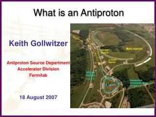
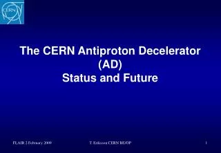
Introduction: Antiproton Decelerator AD – a unique facility providing 5.3 MeV antiprotons (3 107 in <300 ns) Location for future ELENA installation Sketch of the present AD – circumference 182 m - In addition experiment AEGIS installed - Experiment BASE being installed - Gbar approved to receive beam from ELENA • ~1.5 1013 protons (26 GeV) on target • ~3.5 107antiprotons captured in AD • Acceptances 200 mm and ±30 10-3 • Deceleration to the lowest energy 5.3 MeV reachable “safely” (limited by mag. Fields?) • Stochastic and electron cooling at four different energies • ~3 107 antiprotons extracted per cycle • Dense core containing ~70% within <1 mm, often tails up to 10 mm • Longitudinal before bunch rotation95% within 10-4 and 400 ns • Cycle length about 100 s Extra Low ENergy Antiproton ring ELENA IPAC 2014, 17th June 2014
Introduction: Efficiency for capturing antiprotons in traps without and with ELENA 5.3 MeVantiprotons a shotevery ~ 100 sec tooneexperiment ~4 keV antiprotons/ ~ 100 sec ~ 3 x 10⁷ Present situation with AD alone: - Most experiments slow antiprotons down by “degrader” => very inefficient – most (>99%) antiprotons lost (one experiment uses an RFQ for deceleration with higher efficiency) 100 keVantiprotons a shotevery ~100 secsharedby ~4 experiments ELENA ~ .45x 107 Future situation with AD and ELENA decelerating to 100 keV: - thinner “degrader” and increased trapping efficiency (some experiments use other means to decelerate the beam) - Intensity shared by four exp’s allows longer periods with beam Extra Low ENergy Antiproton ring ELENA IPAC 2014, 17th June 2014
ELENA Overview and Layout Extraction towards existing experiments (with fast electrostatic deflector) Line from H- and proton source for commissioning Wideband RF cavity Injection with magnetic septum (≈300 mrad) and kicker (84 mrad) Scraper to measure emittances (destructive) Quadrupoles High sensitivity magneticpick-up for Schottky diagnostic (intensity) and LLRF Electron Cooler and compensation solenoids Extraction towards new exp. zone • Deceleration of antiprotons from 5.3 MeV to 100 keV to improve efficiency of experiments • Circumference 30.4 m (1/6 the size of the AD) • Fits in available space in AD hall and allows installing all equipment without particular efforts • Lowest average field (beam rigidity over average radius) Br/R = 94 G (smaller than for AD 115 G) Extra Low ENergy Antiproton ring ELENA IPAC 2014, 17th June 2014
ELENA Overview and Layout New annex building with kicker equipment Towards existing experiments AD Shielding ELENA ring New area with One approved experiment • ELENA in AD hall with existing (AD experiments) and new experimental area • Cost effective with short transfer line from AD and no relocation of existing experiments • New (small) building to house equipment now at location, where ELENA will be installed Extra Low ENergy Antiproton ring ELENA IPAC 2014, 17th June 2014
ELENA Overview and Layout Transfer line (magnetic)from AD External source for commissioning Electro-static line towardsexisting experimental area Extraction towards new experimental area Extra Low ENergy Antiproton ring ELENA IPAC 2014, 17th June 2014
Selected Features and Issues • Energy Range • Machine operated at an unusually low energy for a synchrotron (down to 100 keV!) • Many points below a consequence of the low energy • Lattice • Constraints • Long straight section with small dispersion for electron cooling • Geometry in AD hall (location of injection and two extractions) • Many geometries and quadrupolelocations investigated • Hexagonal shape and optics with periodicity two • Tunes: QX ≈ 2.3, QY ≈ 1.3(e.g. QX = 2.23, QY = 1.23) • Acceptances: about 75 mm (depends on working point) Extra Low ENergy Antiproton ring ELENA IPAC 2014, 17th June 2014
Selected Features and Issues • Electron cooling • Applied at an intermediate plateau at 35 MeV/c and the final energy 100 keV • To reduce losses during decelerationafter 1st cooling plateau and generatebright bunches for experiments • Electron beam expansion by factor 10 to reduce its temperature • Bunched beam cooling at 100 keVto reduce momentum spread ofshort bunches requested by experiments • Perturbations of magnetic system oncirculating beam under study • Expected main performance limitation: Intra Beam Scattering IBS • Determines beam parameters with cooling(equilibrium between the two processes) Extra Low ENergy Antiproton ring ELENA IPAC 2014, 17th June 2014
Selected Features and Issues • Rest gas interactions and vacuum system • 3 10-12Torr nominal pressure - fully baked machine with NEGs wherever possible • Interactions of beam with rest gas to be evaluated with care (see TUPRI028, MOPRO036) and not a dominant performance limitation • Beam diagnostics with very low intensities and energy • E.g.: Beam currents down to well below 1 mA far beyond reach standard slow BCTs • Intensity of coasting beam measured with Schottky diagnostics • Magnets with very low fields (see TUPRO106) • “Thinning” (mixing of stainless steel and magnetic laminations) for bending magnets and possibly for other small magnets, steerers without magnetic yoke • Careful magnetic measurement with pre-series magnets • Electrostatic transfer lines to experiments (see MOPRI101) • Cost effective at very low energies, easier for shielding against magnetic stray fields • RF system with modest voltages, but very large dynamic range • Direct space charge defocusing a possible limitation despite very low intensity (and 300 ns long bunches) • Split available intensity to several (baseline four) bunches to mitigate • Commissioning with external H- and proton source (and electrostatic acceleration to 100 keV) • Higher repetition rate but start commissioning at the difficult low energy part of the cycle Extra Low ENergy Antiproton ring ELENA IPAC 2014, 17th June 2014
Expected Magnetic Cycle Cooling simulations at 35 MeV/c assumed 8 s plateau p (MeV/c) Time (s) • Ramps • Blow-up due to IBS must remain acceptable (fast ramp) • Perturbation of optics due to Eddy currents must remain acceptable (slow ramp) • Plateaus with electron cooling • Duration taken from simulations of cooling • ELENA cycle expected to last about 25 s, but repetition rate slower (beam from AD about every 100 s) Extra Low ENergy Antiproton ring ELENA IPAC 2014, 17th June 2014
ELENA Beam ParametersPresent best guess combining different Sources erms = sb2/bT with sb the rmsbetatron beam size and bT the Twissbetatron function +) difficult to determine due to (i) dense core and long tails, (ii) variations with time a) Typical values measured with AD – some reduction of long. Emittance with bunched beam cooling b) Increase of voltage from 16 V at transfer to 100 V on ramp c) Simulations of IBS on ramp d) Debunching/bunching with 50% blow-up (bunched with LHC def. eL = 4psEsT, coasting eL = 4 (2/p)1/2sETrev) e) From ELENA technical meetings with presentations by G.Tranquille and P. Beloshitsky Extra Low ENergy Antiproton ring ELENA IPAC 2014, 17th June 2014
New building adjacent to the AD hall • New Building 393 completed in February ahead of schedule • Will house electronics (PFL) for AD and ELENA injection kicker • Storage space .. for experiments • Infrastructure installation ongoing Extra Low ENergy Antiproton ring ELENA IPAC 2014, 17th June 2014
Conclusions, Status and Outlook • ELENA will be a small ring to further decelerate antiprotons from the AD • Electron coolimgto reduce beam emittancesand energy spread • Improvement for existing experiments and new types of experiments (e.g. gravitation) • ELENA Machine to be built well known now • General Project Review last autumn • Concept of decelerator with electron cooling endorsed, no showstoppers identified • Many proposals for further studies and improvements • Technical Design Report TDR describing machine published • Status and outlook • Moving from the conception to implementation phase • First contracts for equipment (magnets …) being signed • ELENA installation in 2nd half of 2015 and beginning 2016 followed by commissioning • Transfer line installation followed by commissioning during 1st half 2017 • First physics run with 100 keV antiprotons from ELENA planned for 2nd half of 2017 Extra Low ENergy Antiproton ring ELENA IPAC 2014, 17th June 2014
Thanks for your attention ! Extra Low ENergy Antiproton ring ELENA IPAC 2014, 17th June 2014
Basic ELENA Parameters Extra Low ENergy Antiproton ring ELENA IPAC 2014, 17th June 2014