Download
1 / 41
410 likes | 553 Views
Psyc 552 Ergonomics & Biomechanics. Lecture 14. Evaluating Lifting with NIOSH. National Institute of Occupational Health & Safety. Created Lifting Equation in 1994. The multiplicative model that computes a Lifting Index (LI). LIs > 1.0 pose greater risk of low back pain.

E N D
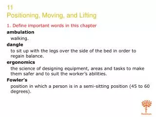
Psyc 552 Ergonomics & Biomechanics Lecture 14
Evaluating Lifting with NIOSH • National Institute of Occupational Health & Safety. • Created Lifting Equation in 1994. • The multiplicative model that computes a Lifting Index (LI). • LIs > 1.0 pose greater risk of low back pain.
NIOSH Equation Components Container characteristics Load weight Vertical location Horizontal location
NIOSH Equation Components • Asymmetry angle • Other Task Measures • Frequency of lifts • Lifting duration
Components to Multipliers RWL = LC x HM x VM x DM x AM x FM x CM • RWL = Recommended Weight Limit • LC = Load Constant (51 lbs) • HM = Horizontal Multiplier • VM = Vertical Multiplier • DM = Distance Multiplier • AM = Asymmetry Multiplier • FM = Frequency Multiplier • CM = Coupling Multiplier
Variables – Horizontal Component • Horizontal Location (H) is measured from the mid-point of the line joining the inner ankle bones to a point projected on the floor directly below the mid-point of the hand grasps (i.e., load center), as defined by the large middle knuckle of the hand. • H = 8 + W/2 for V => 10 inches • H = 10 + W/2 for V < 10 inches • W = width of the container in the sagittal plane and V is the vertical location of the hands from the floor.
Variables – Horizontal Multiplier • HM = 10/H • When H < 10, HM = 1 • When H >25”, HM = 0
Variables – Vertical Component • The vertical location should be measured at the origin and the destination of the lift to determine the travel distance (D)
Variables – Vertical Multiplier • VM is based on the absolute deviation of V from the optimal or knuckle height of an average worker. • VM = 1(.0075|V-30|) – for inches • When V is at 30 inches (75 cm), the vertical multiplier (VM) is 1.0. • If V is greater than 70 inches, then VM = 0
Variables – Distance Component • Vertical Travel Distance variable (D) is defined as the vertical travel distance of the hands between the origin and destination of the lift. • DM = (.82 + (1.8/D)) – for inches • The DM is 1.0 when D is set at 10 inches; DM is 0.85 when D = 70 inches
Variables – Asymmetry Component • Asymmetric angle (A) defined as the angle between the asymmetry line and the mid-sagittal line. The asymmetry line is the horizontal line that joins the mid-point between the inner ankle bones and the point projected on the floor directly below the mid-point of the hand grasps, as defined by the large middle knuckle.
Variables – Asymmetry Component • The asymmetry angle (A) must always be measured at the origin of the lift. If significant control is required at the destination, however, then angle A should be measured at both the origin and the destination of the lift.
Variables – Asymmetry Multiplier • AM = 1-(.0032A) • The range is from a value of 0.57 at 135 degrees of asymmetry to a value of 1.0 at 0 degrees of asymmetry. • If A is greater than 135 degrees, then AM = 0
Variables – Frequency Component • Frequency is: • The number of lifts per minute (F) • The amount of time engaged in lifting (duration) • The vertical height of the lift from the floor.
Frequency Special Considerations • Lifting frequency is the average number of lifts per minute over a 15 minute period. • When work does not require lifting for 15 minutes and the lifting frequency does not exceed 15 lifts per minute then: • Compute the total number of lifts for a 15 minute period – (lift rate X work time) • Divide the total number of lifts by 15 • Use the quotient as the frequency F for the table.
Lifting Example • A job requires: • Lifting for 8 minutes • Light work for 7 minutes • Lift rate for the 8 minutes is 10 lifts/min • The lift frequency F would be: • (10 x 8)/15 = 5.33 lifts/minute
Lifting Duration – Short • Short: <1hour, followed by a recovery time equal to 1.2 times the work time (Rest time / Work time = 1.2). • To be classified as short-duration, a 45-minute lifting job must be followed by at least a 54-minute recovery period prior to initiating a subsequent lifting session.
Lifting Duration – Moderate • Moderate: > 1 hour < 2 hours, followed by a recovery period of at least .3 times the work (Rest time / Work time = .3). • If a worker continuously lifts for 2 hours, then a recovery period of at least 36 minutes would be required before initiating a subsequent lifting session. If the recovery time requirement is not met, and a subsequent lifting session is required, then the total work time must be added together. If the total work time exceeds 2 hours, then the job must be classified as a long-duration lifting task.
Lifting Duration – Long • Long: 2 to 8 hours, with standard breaks (morning, lunch, and afternoon).
Variables – Frequency Multiplier • The FM value depends upon the average number of lifts/min (F), the vertical location (V) of the hands at the origin, and the duration of continuous lifting. For lifting tasks with a frequency less than .2 lifts per minute, set the frequency equal to .2 lifts/minute. For infrequent lifting (i.e., F < .1 lift/minute), however, the recovery period will usually be sufficient to use the 1-hour duration category.
An optimal handle design has .75 - 1.5 inches diameter, > 4.5 inches in length, 2 inches clearance, cylindrical shape, smooth, non-slip surface. An optimal hand-hold cut-out has the following approximate characteristics: > 1.5 inch height, 4.5 inch length, semi-oval shape, > 2 inch (5 cm) clearance, smooth non-slip surface, > 0.25 inches container thickness (e.g., double thickness cardboard). Variable – Coupling Component
An optimal container design has: < 16 inches frontal length, < 12 inches height, a smooth non-slip surface. A worker should be capable of clamping the fingers at nearly 90 degrees under the container, such as required when lifting a cardboard box from the floor. Variable – Coupling Component
A container is considered less than optimal if it has: A frontal length > 16” height > 12” rough or slippery surfaces, Sharp edges, asymmetric center of mass, unstable contents, requires the use of gloves. A loose object is considered bulky if the load cannot easily be balanced between the hand-grasps. A worker should be able to comfortably wrap the hand around the object without causing excessive wrist deviations or awkward postures, and the grip should not require excessive force. Variable – Coupling Component
Variable – Coupling Multiplier • The coupling multiplier (CM) is determined from decision tree and a tabled value.
23” 30” 44# 63” 15” 23”
Manufacturing Punch Press 44 44 23 15 23 63 48 0 0 <.2 <1 Fair
Origin Destination
16.3 .44 .89 .86 1.0 1.0 .95 14.5 .44 .75 .86 1.0 1.0 1.0 Computing RWLs • The RWL for the origin and destination is computed because significant control is required. • Significant control: Precision placement where the worker 1) re-grasps the near the destination, 2) momentarily holds object at destination, or 3) carefully positions load at destination.
Computing Lifting Index 44 2.7 16.3 44 3.0 14.5 • LIs > 1 indicate increased risk of low back pain.
16.3 .44 .89 .86 1.0 1.0 .95 14.5 .44 .75 .86 1.0 1.0 1.0 Redesign the Job • Bring load closer to the body – rotate it 90 degrees. • Lower destination height. • Reduce travel distance. • Eliminate significant control.
The reel is 12” wide. 23” 30” 44# 63” 15” 23”
Modifications 35.1 1.0 .89 .86 1.0 1.0 .90 24.6 .83 .75 .86 1.0 1.0 .90 44 1.3 35.1 44 1.8 24.6
NIOSH Equation Limits • The model DOES NOT apply when lifting or lowering: • With one hand • Over 8 hours • While seated or kneeling • In restricted work space • Unstable objects • Wheelbarrows or shovels • With high speed motion • With unreasonable foot to floor friction • In unfavorable environments (66-79 degrees and 33 to 50% humidity)