Download
1 / 59
620 likes | 1.06k Views
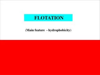
FLOTATION. ( Main feature - hydrophobicity). Flotation. gas bubble. water. . particle. Contact angle. Contact angle of selected materials. Methods of measurement. There are different models of flotation including mechanistic, thermodynamic and probabilistic models.

E N D
FLOTATION (Main feature - hydrophobicity)
gas bubble water particle Contact angle
There are different models of flotation including mechanistic, thermodynamic and probabilistic models
The simplest model of flotation Thermodynamicapproach Gflotation= Gfinal- Ginitial = [sg - (sc+ cg)] A for A = = 1cm2 surface area Gflotation= sg - (sl+ lg) Dupre eq. (1869)
Gflotation = sg - (sl+ lg) Dupre eq. (1869) where G – thermodynamic potential (free enthalpy, Gibbs potential) sg – solid – gas interfacial energy sl – solid – liquid interfacial energy lg – liquid – gas interfacial energy unit of energy and potential G isJ/m2
is measured through the aqueous phase The Young Equation sg = sc+ cgcos - contact angle
Combination of the Dupre Gflotation = sg - (sl+ lg) and the Young eq. sg = sl+ lgcos provides the Dupre-Young eq. G flotation = lg(cos - 1) = 0o, cos = 1, G=0, no flotation, = 90o, cos = 0, G= -cg, hipothetically full flotation Main parameter of separation – contact angle
main parameter of flotation (resulting from the simplest flotation model) contact angle (a measure of hydrophobicity ) the Dupre-Young eq. Gflotation = lg (cos - 1) process energy main feature „electromagnetic field” of separation (flotation) system
More detailed models of flotation Particle and spherical bubble here flotation also depends on and
other models take into account other parameters such as size of bubble and particle
Probabilistic models for instance Schulze (1993) dNp /dt = –k Np. (first order kinetics k = Pc Pa Pstab PtpcZNb c=[2R3p(p+ 1,5)/3]0,5(1,39 – 0,46 ln Rp) i = 3R2FRp/8cbh2crit hcrit = 23,3[ (1 – cos A)]0,16 Bo’=4R2p(g + pa) +3Rp(sin2 *) f (Rb)/C C = 6 sin *sin (* + ), * 180° – /2 f(Rb) = (2/Rb) – 2Rbg v = 0,6(Rp + Rb)2/ (laminar) v= 13(Rp + Rb)2/3/*1/3 (turbulent )
dN/dt – flotation rate, a – centrifugal acceleration acting on particle-bubble aggregate in a vortex of liquid, Bo´ – Bond’s number, cb – rigidity of bubble surface (cb = 1 for rigid uneven surface, cb < 1 for movable smooth surface), Cb – bubble concentration in pulp (number of bubbles in 1cm3 of pulp), E – efficiency of attachment of particles to bubble surface (number of attached particles divided by the number of particles colliding with considered bubble), E1–energy barrier for adhesion of bubble and particle, Ek – kinetic energy of collision of bubble with particle, Ek´ – kinetic energy of detachment of particle and bubble (calculated from the French–Wilson Eq.), g – acceleration due to gravity, hkryt – critical film thickness on surface of particle, k – rate constant of flotation, Nb – number of bubbles in flotation cell at a considered time, Np – number of particles subjected to flotation at a considered time, Pa – probability of adhesion of particles to a bubble, Pd – probability of detachment of particles from a bubble (Pd = 1 – Pstab), Pstab – probability of stability of particles-bubble aggregate, Ptpc–probability of formation of particle-bubble-water contact, Q – flow of air in flotation machine, m3/s, Rp – particle radius, Rb – bubble radius, Rc – radius of the stream enabling collision of particle with bubble, RF – size of thin film between particle and bubble during collision, Re – Reynolds number, S – cross section area of flotation machine, m2, Sb – area of bubbles leaving flotation cell per time unit and per cross section area ot the cell, V – rate of ascending bubble, m/s, Vb –surface velocity of aeration defined as volume rate of aeration normalized per cross section of the flotation column, U – velocity of particles in relation to velocity of bubble in the pulp, Z – number of particle collisions per unit time, – surface tension of aqueous solution, – quantity characterizing efficiency of collision between particles and bubbles, * – dissipation energy in flotation cell, – effective density of particle in water, – dynamic viscosity, – kinematical viscosity, – pulp density, p – particle density, – contact angle, A – advancing contact angle, v – life time of liquid vortex in flotation cell which destroys the particle–bubble aggregate, tpc – time needed to form permanent three-phase solid-gas-liquid contact, c – collision time of bubble and particle, i – induction time (time of removing liquid film from particle and forming attachment), min – minimal time of contact, = 3.14, * = 180 – /2.
receding qr water advancing qa water q equlilibium flotacja 4
sg = sc+ cgcos g cg vapor adsorption liquid drop c scg sg x x x x x x x x x x x x x x x s s s - = sc+ cgcos the Young equation
FLOTATION depends on hydrophobicity hydrophobicity is measured as contact angle
Electrical aspects of flotation naturally hydrophobic
Electrical aspects of FLOTATION Main parametr – hydrophobicity (contact angle) which depends on energetics of three interfaces (Young eq.) sg = sl+ lgcos the Gibbs theory tells that • adsorption • chemical potential R gas constant, F Faraday cost. a activity (concentration) • surface charge • surface potential • temperature (d)T = (–idi)T. di = RT d ln ai,
FLOTATION main feature field (el.-mag.) Hydrophobicity : contact angle g D q G = (cos –1) q cg ( g g g q (cos = + )/ ) sg sc cg * g g g dg d s / E= – cg, sg, sc G s Y , , s ( Y = f ) G d g /d =–(1/R T ) ln a Potential: electrical E , Chemical ln a (oraz pH, pX, ....) f (activity coeff. electrochemical E h a = f c c c c c c c , , , , bubbles collector frother salt other particles *Young eq. flot
Electrical aspects of flotation -+ -+ water moving particle + - + - -+ - + - - + - + + slipping plane zeta potential -+ -+ -+
triple layer Helmholz (flat condenser) Stern (rigid and diffuse layer ) quadruple layer Gouy-Chapman (diffuse layer) Grahame (binding sites) o o o i o i d o i d o o oijd H+ K+ K+H2O OH- A- A-H2O od ----- H+ OH- o id----- H+ OH- o -o H+ OH- oid---- H+ K+ OH- A- Models of electrical double layer 0 = 0 0 Flat condenser Diffuse condenser
Formation of electrical double layer surface charge negative positive metals ęć Me Me Me Me Me Me Me Me Me Me Me Me Me Me Me - Me Me Me Me Me Me Me Me H2O + n Me+ + electrons or oxides Me O Me O O Me O Me Me O Me O O MeO- Me OH O MeO- O MeOH2+ Me OH O MeOH2+ H2O + n H+ + n OH- or salts Me X Me X X Me X Me Me X Me X Me X X - Me X X Me Me+ X Me H2O + n X- + n Me+ or place of particle breakage particle /water interface
lad ½ ½ ½ ½ ½ ¾ ¾ ¾ ¾ ¾ ¾ ¾ ¾ S Me OH Me S Me S ½ ½ ½ ½ ½ H O 2 ¾ ¾ ¾ ¾ ¾ ¾ ¾ Me SH S Me S Me ½ ½ ½ ½ ½ ¾ ¾ ¾ ¾ ¾ ¾ ¾ ¾ S Me OH Me S Me S ½ ½ ½ ½ ½ other ½ ½ + ¾ ¾ ¾ S Me OH ¾ ¾ ¾ S Me OH 2 ½ ½ - + - ¾ ¾ Me S + n OH + H ¾ ¾ Me SH ½ ½ ¾ ¾ ¾ S Me OH + ¾ ¾ ¾ S Me OH ½ 2 ½ Formation of electrical double layer
interpretation: preferential adsorption of -OH groups 20 0 -20 D O-ice ( ) (0.0001M) n 2 · diamond ( ) zeta potentia, mV -40 air ( ), ( ) Nocardia sp. w « -60 hexadecane D O-ice (0.001M) 2 -80 2 4 6 8 10 12 pH zeta potential and iep for materials without functional groups
Flotation reagents COLLECTORS for hydrophobization FROTHERS for froth creation MODIFIERS for enhancing
hydrophobization: with all possible chemical bondings COLLECTORS Possible modes of adsorption of collectors at particle-water interface: a – adsorption of oil on hydrophobic particle with van der Waals forces, b – adsorption of apolar molecule of collector by means of hydrogen bonding, c – adsorption of polar collector by means of simple chemical bond or electrostatic attraction, d – adsorption with formation of chelating bond. Hydrophobic part of the collector is shown in white while hydrophilic as black Not to scale.
CH3CH2CH2CH2 CH2CH2CH2CH2 COO– tail (hydrophobic) head (hydrophilic) Structure of collector CMC Collector ions can be present in aqueous solution as free ions (a), premicellar species (b) spherical micelles (c). The structures appear with increasing concentration of collector in aqueous solution. Symbol o denotes ion appositively charged to the collector ion
An example of lack of correlation between CMC and flotation (after Freund and Dobias, 1995). SOS – sodium octyl sulfate, SDS – sodium dodecyl sulfate
Adsorption of ionic collector on the surface of particle with the formation of hemimicelle (a), monolayer (b) and a second layer leading to hydrophilicity (c)
Maximum contact angle for different collectorswith ethyl and butyl chain. After Gaudin, 1963 * For methyl chain (C1) 50°, propyl (C3) 68°, C5 78°, C6 81°, for greater about 90°, and for C16 98° (Aplan and Chander, 1988).
collector renders the surface hydrophobic gas collector particle
Flotation of particles increases with increasing concentration of collector in the system and is proportional to collector adsorption and hydrophobicity caused by the adsorption. Collector adsorption is manifested by the increase of zeta potential of particles (after Fuerstenau et al., 1964 and Fuerstenau and Urbina, 1988), pH = 6–7
Which interface is responsible for hydrophobicity increase with collector addition? Dependence of contact angle and the state of mercury at interfaces on concentration of collector Data by Smolders (1961) taken from various sources: contact angle in dodecyl sulfate solution and H2O (dodecyl sulfate) (Leja, 1982), Hg /H2O(decyl sulfonate) and Hg (decyl sulfonate) (de Bruyn i Agar, 1962))
Flotation is influenced by reagents modifying the interfaces. Collectors strongly change the solid-gas, surfactants water–gas, and electrolytes (pH reagents and salts) solid–water interfaces. The extent of modification is expressed by the height of symbol