Download
1 / 33
330 likes | 345 Views
Explore the Hadron Collider developments from Tevatron to VLHC Stage 2, focusing on IR design issues, R&D programs, beam-beam interactions, and energy deposition challenges.

E N D
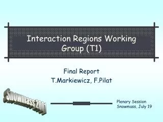
Interaction Regions Working Group (T1) Final Report T.Markiewicz, F.Pilat Snowmass 2001 Plenary Session Snowmass, July 19
Overview • Introduction • Hadron colliders • Lepton-hadron • e+e- linear colliders • gg collider • e+e- ring colliders • m-m colliders • Conclusions
Hadron Colliders Review Tevatron, RHIC operational experience, LHC design VLHC Stage 1 and Stage 2 Hadron IR issues • IR designlayout, flexibility, upgrade • IR componentsmagnets, powering • IR performanceLR beam-beam, field quality, alignment • IR correctionslocal, feedback, beam-beam compensation • Energy depositionbackground, IR component protection • Integrationmachine-experiment R&D program
IR design – VLHC Stage 1 • Triplet optics (antisymmetric) • Triplets : 300 T/m • 4 matching quads 70 T/m • Dm fixed • b* : 6 0.3 m • Crossing angle +/- 77 mrad • 10 s at the first parasitic crossing R&D: IR magnets (M.Lamm, S.Zlobin, T2): LHC upgrade: Nb3Sn 250 T/m 90mm bore VLHC-1: Nb3Sn 300 T/m 70mm bore Goal: short model FY05-08 ~10M$ prototype FY08-10 ~20M$
IR design – VLHC Stage 2 • Doublet (flat)– symmetric • Doublet 400-600 T/m • Dm fixed • b*v : 7.12 0.37 m • b*h : 71.2 3.7 m Triplet solution exists, similar to Stage 1 optics • Flat opticsseparate, then focus • Final doublet design challenging: • 2-in-1, high gradient, neutral debris • R&D: (M.Lamm, R.Gupta, B.Parker, T2): • double bore HTS IR quads 400-600T/m • Separation dipoles 12-16 T Goal: short model by FY12-16
Flat round optics Flat beam pro’s: LR horizontal tune shift 20x smaller LR vertical tune shift 2Xsmaller Flat beam con’s: doublet magnet design Neutrons from IP hit the conductor Lack of (lower) energy flexibility flat ‘round’ Snowmass result (J.Johnstone): Optical solution with 4 FF IR quadrupoles exists that allows continuous transition from flat (doublet) to round (triplet) - very attractive! R&D: optimization of design development of FF quadrupoles
IR Correction Systems • To relax tolerancescost effective design • To improve operational performance • R&D: Development of a collaborative beam experiment program at existing laboratories (Snowmass conclusion, M4-T1) in the next 3-6 years to address: • beam-beam (LR, coherent modes, etc.) • test of compensation schemes • IR correction and feedback • IBS, diffusion, …. Phase 1: MD activity Phase 2: formally approved experiments LHC inner triplet and local correctors
Energy deposition • LHC • ~900 W/IR side of collision debris • generated at nominal E and L • Machine background few % if IP debris • VLHC-1 • ~ 3 KW/IR side of collision debris • factor 3 – extrapolation is OK VLHC-2 • Extrapolation not OK • ~24 KW/IR side of collision debris (initial PHYTHIA simulation) R&D: • Modeling (MARS, PHYTHIA) • Development of IR protection system (collimators, absorbers, etc.) From Nikolai Mokhov LHC Heat Load
Lepton-hadron colliders • HERA (HERA upgrade) eRHIC, EPIC, THERA • IR Panel on e-hadron IRs (Keil, Peggs, Merminga, Willeke, Norem, Hasell, Krasny) • Luminosity • Collision frequency optimization among conflicting requirements • Accelerator-experiment integration (components – teams) background, collimation, vacuum, alignment, instrumentation • Head-on vs crossing angle • SR and backgrounds • Energy range energy tunability essential to match the physics R&D: • Optimization of collision frequency • IR FF magnets extensive experience for HERA upgrade inside detector, large aperture, holes for other beam good field quality, local correction coils • Electron cooling for proton beams
Basic LC IR Drivers • Bunch Structure: • Beam-beam effects • Small spot sizes: Crossing Angle & Feedback Design IP Backgrounds & Pinch Enhancement Control position & motion of final quads and/or the beam
Backgrounds and IR Layouts • Most important background is the incoherent production of e+e- pairs. • # pairs scales with luminosity and is ~equal for both designs. • Detector occupancies depend on machine bunch structure and relevant readout time • GEANT and FLUKA based simulations indicated that in both cases occupancies are acceptable and the CCD-based vertex detector lifetime is some number of years. • IR Designs & Magnet Technologies • Differ due to the crossing angle, magnet technology choice, and separate extraction line in the case of the NLC • Similar in the use of tungsten shielding, instrumented masks, and low Z material to absorb low energy charged and neutral secondary backgrounds
e+,e- pairs from beams. gg interactionsare the most important background # scales w/ L 2.5-5x10⁹/sec BSOL, L*,& Masks
NLC Detector MaskingPlan View w/ 20mrad X-angle Large Det.- 3 T Silicon Det.- 5 T 30 mrad 32 mrad
JLC IR8 mrad Design Elevation View • Iron magnet in a SC Compensating magnet • 8 mrad crossing angle • Extract beam through coil pocket • Vibration suppression through support tube
Detector Occupancies are Acceptablefn(bunch structure, integration time) TESLA VXD Hits/BX vs. Radius LCD=L2 Hit Density/Train in VXD &TPC vs. Radius TESLA #g/BX in TPC vs. z
TESLA SC Final Doublet QuadsMature LHC based Design • QD0: • L=2.7m • G=250 T/m • Aperture=24mm • QF1: • L=1.0m
NLC Final Doublet QuadsCompact, stiff, connection free Permanent Magnet Option EXT QD Carbon fiber stiffener nm-mover FFTB style cam movers Cantilevered support tube T2: Compact SC (HERA-style)
Extraction and DiagnosticsHandling the Disrupted Beam NLC Post-IP Diagnostics Common g,e dump TESLA Pre-IP Diagnostics Separate g & e dumps
Colliding Small Beam Spots at the IP Q1 Q1 Relative Motion of two final lenses e+ e- sy ~ 3-5 nm Dy = sy/(4-10) ~ 0.5-1 nm • Control position & motion of final quads and/or position of the beam to achieve/maintain collisions • PASSIVE COMPLIANCE: Get a seismically quiet site, don’t screw it up (pumps, compressors, fluids), engineer the quad/detector interface • FEEDBACK: Between bunch trains & Within bunch trains • SENSE MOTION & CORRECT MAGNETS or BEAMS
Intra-train Feedback based on beam-beam deflection at TESLA Dy~25 ~0.1s~0.5nmsensitivity In 90 bunches and DL < 10%, bunches are controlled to 0.1sy
Very Fast Intra-train IP Feedback at NLC limits jitter-induced DL Concept Design Performance 5 s Initial Offset (13 nm) YIP (nm) 40ns Latency
R&D on Inertial Stabilization to Suppress Jitter at NLC Block with Accelerometers/ Geophones & Electrostatic Pushers x10-100 Jitter Suppression in Frequency Range of Interest
R&D on Interferometers to Stabilize Quads w.r.to Tunnel Sub-nm resolution measuring fringes with photodiodes drive piezos in closed loop Measured Displacement over 100 seconds rms = 0.2nm UBC Setup
gg Collider IR Laser Development • Fusion program-funded “Mercury” laser project applicable to gg project is under construction • Conceptual designs to take the output of the laser and to match it to the time structure required for either the NLC or TESLA are underway IR Optical designs • to provide the ge collisions have been developed and will soon be tested. Optics and IP parameters • improved performance for gg collisions
Mercury power amp Mercury power amp Mercury power amp LLNL 10Hz -100J “MERCURY” Fusion Program Laser IS Prototype for gg Collider g-g laser system architecture: CPA front end seeds 12 Mercury power amplifiers Mode-locked oscillator Spectral shaper Stretcher OP-CPA preamp 0.5 J 3 ns 120 Hz 12- 100 J power amplifiers Optics: Combiner, splitters Beam splitters 100 J macropulse: 100X 2ps micropulses 120 Hz Grating compressor
Diode pulsers Front end Gas-cooled amplifier head Pump delivery Injection multi-pass spatial filter
Matching Laser Output to Accelerator Bunch StructureKnown Technology – gg specific development planned 8 May 1999
Large Diameter gg Annular Optics Engineered Performance Tests Planned Out of the way of input beam & beam-beam debris
Circular e+e- IRs • HOM • SR • SR Masks • Beam Tails • Orbit Compensation
mm Collider IR Final Focus design using local chromatic correction scheme of NLC Shielding designs tuned for 100 GeV, 500 GeV, and 4 TeV
Conclusions Many IR design issues are common across different types of machines VLHC IR design has advanced, with the promise of both round and flat beam solutions. R&D for IR magnets and correction systems are priorities. The proposed designs for LC IRs look more similar than different, are fairly well advanced, and have active R&D programs Viable solutions to gg Laser & IR Optics now available and give program real credibility
NLC/TESLA Beam-Beam Comparison • Larger sz for TESLA • More time for disruption • larger luminosity enhancement • more sensitivity to jitter • Lower charge density • lower energy photons • Real results come from beam-beam sim. (Guinea-Pig/CAIN) and GEANT3/FLUKA