Download
1 / 27
320 likes | 577 Views
General Electric T-700 Engine Overview. Presented by CW2 Keith Koca UH-60 IPC Class 99-06. Objective. Develop Student Instructor Pilot’s understanding of the T-700 Engine and it’s related components.

E N D
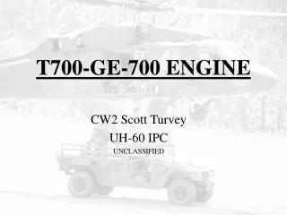
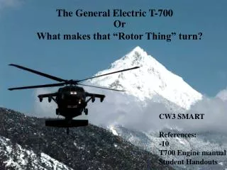
General Electric T-700 Engine Overview Presented by CW2 Keith Koca UH-60 IPC Class 99-06
Objective • Develop Student Instructor Pilot’s understanding of the T-700 Engine and it’s related components. • The Student Instructor will utilize fundamentals of instruction (FOI) from the IP handbook for the class. • The Student Instructor will utilize the Guided Discussion method of teaching.
Topics of Discussion • General Engine Components, and Engine Modules • Engine Alternator • Electrical Control Unit (ECU) • Hydromechanical Unit (HMU) • Pressurizing and Overspeed Unit (POU) • Np Overspeed Protection • Engine/Inlet Anti-ice System
T-700 General Engine Components, and Engine Modules • Students will identify engine components • Students will identify engine sections I.E. Power Turbine Section, Hot Section. • Refer to Engine Overhead Projections.
Engine Alternator • Location • It supplies AC power to engine components and a signal to a Signal Data Converter (SDC) to represent a cockpit instrument indication. • Three internal stator (Stationary) windings that provide three functions.
Engine Alternator • What will happen if the Ng signal is interrupted? • What will happen with a complete alternator failure? • What will happen if the ignition power from the alternator is lost?
Engine Alternator • Emergency Procedure: Increasing % RPM R • Warnings: Single and Dual Engine failure
Electronic Control Unit (ECU) • 7 Functions: • Acronym S - C - O - R - E I - T
Electrical Control Unit (ECU) • S - Signals to the History Recorder. • C - Cockpit Indications: Np, TGT, TRQ • O - Overspeed Protection: 106%NP • R - Reference Signal, NP set by pilot using the incr/dec switch on either collective. Can be set 96 to 100 %. • E - Engine Torque Matching - Q1, Q2 signal, lower torque engine matches higher torque engine up to 103 % Np.
Electrical Control Unit (ECU) • I - Isochronous Np Governing: ECU will maintain a constant reference Np speed set by the pilot. Isochronous means: “Equal in duration”. • T - TGT Limiting: 837 - 849 degrees C, the ECU will send a signal to the HMU Torque Motor to reduce to fuel flow to the engine.
Electrical Control Unit (ECU) • Emergency Procedures -Decreasing RPM R -Increasing RPM R -% RPM Increasing/Decreasing Oscillation -%TRQ Split Between Engines 1 - 2
Hydromechanical Unit (HMU) • 9 Functions • Acronym N - P - M T - O C - A - V - E
Hydromechanical Unit (HMU) • N - Ng Limiting: Limits Max Trq Avail during low temperatures (OAT). • P - Pumps Fuel: High pressure for precise fuel spray pattern, approx. 832 PSI Operating, Ref. GE 700 Training Guide. • M- Meters fuel flow to the POU in response to PAS pos., LDS pos., ECU, T2, P3, and NG.
Hydromechanical Unit (HMU) • T - Torque motor to trim engine Ng output. • O - Overtravel of the PAS to allow fuel system priming.
Hydromechanical Unit (HMU) • C - Collective pitch compensation through LDS. • A - Acceleration and deceleration fuel flow limiting. • V - Variable geometry positioning. Positions IGV’s and variable stator vanes. • E - ECU inoperative: PAS Override to manually control engine.
Hydromechanical Unit (HMU) • Emergency Procedures: - Increasing % RPM R - Engine Compressor Stall
Pressurizing and Overspeed Unit (POU) • Sequences start fuel to primer nozzles for engine starting. • Purges fuel from primer nozzles after starting to keep fuel from coking inside nozzles. P3 air purges primer nozzles. • Sequences main fuel to fuel injectors for starting acceleration and engine operation.
Pressurizing and Overspeed Unit (POU) • Purges main fuel manifold after shutdown. -Residual combustion chamber pressures (P3) forces the fuel in the injectors and manifold back through the unit and out the overboard drain line.
Pressurizing and Overspeed Unit (POU) • Np Overspeed Protection: -POU reduces fuel to the engine during engine overspeed, 106% Np, when the overspeed system is tripped by the ECU. - In the event of an alternator failure Np overspeed protection is still available, due to redundant electrical power provided to the ECU for Overspeed protection.
Pressurizing and Overspeed Unit (POU) • Emergency Procedures - Increasing % RPM R
Engine Anti-ice System • Two Engine Anti-ice Systems: - Bleed air (stage 5 Compressor air) routed to the swirl frame and front frame for front of engine anti-icing. Another branch of anti-icing air is utilized to heat the IGV’s. - Hot engine oil passing within the scroll vanes also prevents icing.
Engine Anti-ice System • When the anti-ice valve is open, the ENG ANTI-ICE advisory light will be illuminated. • In the event of electrical failure, the anti-ice valve will open allowing engine anti-ice protection.
Engine Inlet Anti-ice System • Stage 5 compressor bleed air is directly routed to the Engine Inlet Anti-ice Modulating Valve. • With the Engine Anti-ice switch in the on position and OAT below 4 deg. C, the modulating valve will open and provide anti-ice protection to the engine inlet. -Note: 4 - 13 deg. C the modulating valve may or may not open.
Engine Inlet Anti-ice System • Inlet anti-icing will turn on if DC primary bus power loss occurs. Valve is electrically held closed. -Temperature must still be below 4 deg. C for valve to open. • ENG INLET ANTI-ICE ON advisory light will illuminate when inlet fairing temperature reaches 93 deg. C.
Engine/Inlet Anti-ice System • Emergency Procedures -Single/Dual Engine failure • Warning - Engine HIT Check • Caution - Engine FOD, 2 Cautions, chapter 2/8
Summary/Review • General Engine Components, and Engine Modules • Engine Alternator • Electrical Control Unit (ECU) • Hydromechanical Unit (HMU) • Pressurizing and Overspeed Unit (POU) • Np Overspeed Protection • Engine/Inlet Anti-ice System
T-700 Engine • QUESTIONS?