Download
1 / 45
450 likes | 615 Views
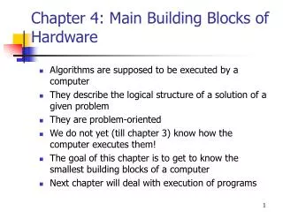
Chapter 4: Main Building Blocks of Hardware. Algorithms are supposed to be executed by a computer They describe the logical structure of a solution of a given problem They are problem-oriented We do not yet (till chapter 3) know how the computer executes them!

E N D
Chapter 4: Main Building Blocks of Hardware • Algorithms are supposed to be executed by a computer • They describe the logical structure of a solution of a given problem • They are problem-oriented • We do not yet (till chapter 3) know how the computer executes them! • The goal of this chapter is to get to know the smallest building blocks of a computer • Next chapter will deal with execution of programs
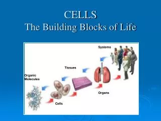
Main Building Blocks of Hardware • We will deal with the: • Representation of numbers • Boolean Logic • Gates • Comparison with biology: • This chapter will have microscopic view and will handle tiny objects like cells, DNA, tissues, and genes in biology. • The big picture, including heart, lungs and other organs as well as their interconnections will be deferred to the next chapter. • This field of computer science is called hardware design or logic design
Binary Numbers • How is information represented in a computer? • Information vs Data • First, humans also represent information: • Numerical values: 10 digits (0..9) • Textual information: 26 letters (A..Z) • Sign-magnitude notation: + and – (left to digits) • Decimal notation: using decimal point separating 2 whole numbers where the right one is positive e.g –12.56
Binary Numbers • Computers? • External representation • Internal representation • External: • Looks like human representation • Important is the internal representation: • The way information is stored in memory • Internally computers use the binary numbering system • Example: • Input via keyboard: ABC • Memory representation: e.g. 0100101001010101101010100 • Output to screen: ABC
Binary Numbers • What are binary numbers? • Base-2 positional number system • In everyday life we use base-10, where the digit itself as well as its position in a number determine the value of each digit • Moving from the right to the left the positions represent • Ones: 100 • Tens: 101 • Hundreds 102 • Thousands 103 • Example: 3049 = 3*103 + 0*102 + 4*101 + 9*100 • Similarly: Binary numbers use the same idea, except that we have 2 digits only 0 and 1
Binary Numbers • Binary numbers: • 2 digits: with symbols 0 and 1 • Value is based on powers of 2 (not of 10) • The two digits 0 and 1 are called bits (binary digits) • Example: 111001 = 1*25 + 1*24 + 1*23 + 0*22 + 0*21 + 1*20 = 32 + 16 + 8 + 0 + 0 + 1 = 57 • Computation is easier than base-10: simply sum up any non-zero term • Theoretically, any number in the decimal system can be represented in the decimal system and vice versa • This means: We do not loose anything if we use binary notation. Humans use base-10 because it is more compact.
Binary Numbers • Computers always have a maximum number of digits (to represent numbers) • Examples: 16, 32, 64 bits • Example: maximum value is 16 bits long: Max = 1111111111111111 (16 ones) (compare: 999999 is the maximum mileage value if you had 6 positions in your decimal odometer) Max = 215 + ….+20 = 65535 • If an operation in a computer produces a value larger than the maximum value, an error called arithmetic overflow occurs. • Attention: in computer science there are always upper limits for numbers unlike mathematics.
Binary Numbers • Representing negative binary numbers: • Sign-magnitude notation (and others) • Sign-magnitude: the first bit on the left side is used to indicate the sign of the number: • First bit = 1 negative number • First bit = 0 positive number • This means that no extra symbols ‘+’ and ‘–’ are used internally! • Example: representing –49 (if we had 7 bits only) 1 1 1 0 0 0 1 = - (25 + 24 + 20) = - (32 +16 + 1) = -49 • Hence: -49 is represented as 1110001
Binary Numbers • How the computer knows that 1110001 is –49 and not the 8-bit number 1110001 = 26 + 25 + 24 + 20 = 64 + 32 + 16 + 1 = 113 • In other words how to differentiate between 113 and – 49? • In fact, the computer does NOT know whether or not this sequence of 8 bits is a –49 or 113 • Only the context makes it possible to make a difference: Example: “ball” may mean the object used to play or a formal party. Only the context lets us make a difference.
Binary Numbers • Representing Text • Binary digits are also used for text • Any letter of the alphabet is assigned a unique number code mapping • The binary representation of that number is stored in memory instead • Internationally used mapping: ASCII (American Standard for Information Interchange) • ASCII uses 8 bits for each printable symbol (including letters) • Examples: • A 65 01000001 • a 97 01100001 • ? 63 00111111 • Z 122 01111010 • Again: How to know whether e.g. 65 is an ‘A’ or the number 65? Context
Binary Numbers • Why binary? • Why don’t we use decimals also internally? • Binary representation is more reliable • Information is stored using electronic devices depending on electronic quantities like current and voltage. • Using binary means we only need two stable energy states • Using decimals would mean to provide 10 stable energy states, which could be a very tricky and time-consuming engineering task. • Suppose we can store electrical charges between 0 and +45 volts Decimal-to-Voltage Mapping Binary-to-Voltage Mapping 0 [0, 3] 0 [0, 22] 1 [3, 6] 1 [22, 45] 2 [6, 9] …
Binary Numbers • Since voltage may oscillate, a decimal value representing 2 may drop to 6 volts • how to interpret it, as 1 or as 2? • In the case of binary representation, there are only two large ranges (instead of several small ones) and it is therefore very improbable that the voltage drops or rises in a confusing way. • Therefore, we speak of the reliability or stability of the binary representation • Devices that operate on two stable states are called bi-stable ones. • However, there is (theoretically) no argument against using decimal numbers for computers if we were able to construct devices having 10 stable states.
Binary Numbers • Example of bi-stable states: • Full on – full off • Fully charged – fully discharged • Charged positively – charged negatively • Magnetized – non-magnetized • Magnetized clockwise - magnetized counterclockwise • Example for binary: • 0 = 0 volts = full off • 1 = +45 volts = full on • Only large drifts of voltages may influence data
Binary Numbers • Requirements for any hardware device of a binary computer: • 2 stable energy states • States are separated by a large energy barrier • It is possible to sense the state of the device without destroying the stored value • It is possible to switch the state from 0 to 1 and vice versa • Examples: • On-off light switch (clearly not used to build computers) • Magnetic cores (no longer used) • 1955-1975 in use • “core memory”
Binary Numbers • Cores • The 2 states for 0 and 1 are based on the direction of the magnetic field • Current left-to-right counterclockwise magnetization (0) • Current right-to-left clockwise magnetization (1) Direction of magnetic field Direction of magnetic field current Binary 1 Binary 0
Binary Numbers • Transistors • Typical density for cores: 500 bits/in2 • Today’s computers: millions of bits and more • Transistors are more compact, cheaper, require less power • Transistor is like a (light) switch • Off state: no electricity can flow • On state: electricity can flow • Unlike light switch: no mechanics • Switching is done electronically • Fast switching: 10-20 billionth of sec • Density: several millions of transistors / cm2 • Are based on semiconductors: silicon or gallium arsenide • Huge number of transistors on a wafer form so-called integrated circuits (IC) • ICs are also called chips • Chips are mounted inside a ceramic housing called dual in-line package (DIP) • Input/output connectors of DIPs are called PINs
Binary Numbers • DIP are typically mounted on a circuit board (connecting different chips) • Production not mechanically but rather photographically (using light) • More effective (use of masks and simple reuse) • Higher density • More accurate • Very high densities: 5-25 millions transistors/cm2 possible (very large scale integration or VLSI) • Ultra large scale integration or ULSI in progress • All these advantages together shifted computers from being expensive huge devices (filling rooms) to tiny (0.25 cm2) and cheap (ca. $100) processors with millions of transistors, which are far more powerful than the old machines.
Binary Numbers Individual transistors IC DIP PINs Bus Circuit board
Binary Numbers • Theoretical concepts behind transistors: semiconductors • Electrical engineering • Physics • Here we use a model of a switch for a transistor: Switch • Base = high voltage (1) • switch closes • transistor is in “on” state • Base = low (0) • Switch opens • Transistor is in “off” state Collector Emitter Base (control)
Binary Numbers • The two states of a transistor: Switch is open Switch closed Power supply (+5V) +5V Power supply (+5V) 0V Measuring device Measuring device 1
Boolean Logic • Computer circuits construction is based on mathematics: Boolean logic • Relationship: • Truth value “true” represents binary 1 • Truth value “false” represents binary 0 • Anything stored as a sequence of 0 and 1 can be viewed as a sequence of “true” and “false”. • Hence: These values can be manipulated using Boolean operators • Bool George: • English mathematician of mid 19th century • 1854 his book: Introduction to the Laws of Thought • Combined principles of logic with algebra • At his time his book got no special attention but 100 years later his ideas were used for computer design, now there is a branch of mathematics called Boolean algebra.
Boolean Logic • Boolean expressions • Any expression that evaluates to true or false • Examples: • X = 1 • A < B • It is exactly 2 pm now • Operations for arithmetic are: + * / - • Operations for Boolean logic are: AND, OR, and NOT • Rules: a and b are Boolean expressions • a AND b is true iff both a and b are true • a OR b is true if either a is true, or b is true, or both are true • NOT a is true iff a is false
Boolean Logic • Truth table for AND a b a AND b (also written a.b) true true true true false false false true false false false false • Truth table for OR a b a OR b (also written a+b) true true true true false true false true true false false false
Boolean Logic • Example for AND • Check if the weight w of an object is between 90 and 100 kg • W >= 90 does not suffice 130 does not match • W <= 100 does not suffice 45 does not match • We have to build the following Boolean expression: • (W >= 90) AND (w<= 100) • Example for OR • Looking for students majoring in either computer science or biology • Test for major = computer science does not suffice • Test for major = biology does not suffice • OR expression needed: • (major = computer science) OR (major = biology) • Example for NOT • GPA should not exceed 3.5 using “>” operator • NOT (GPA > 3.5)
Gates • Why Boolean logic at all? • Gates are constructed using Boolean logic • Gate: • A device that transforms a set of binary inputs to one binary output • In general, a gate can do any transformation, but we will only deal with 3 gates: • AND gate • OR gate • NOT gate • Computers can be built using only these 3 gates (thanks to Boolean algebra)
Gates • Representation of the 3 gates looks like: a a a a.b a+b a b b • We use the following (and similar) representation(s): a a a a+b a.b OR a NOT AND b b • a, b Î {0, 1} with interpretation similar to {false, true} • Example 0.0 = 0, 0.1 = 0, 0+1=1, not(1) = 0 • Often also Ù, Ú, and Ø are used instead of., +, and -
Gates • Construction of an AND gate • Idea: 2 transistors in series • Current flows iff both transistors are closed (state 1) Output (a.b) Power Supply Input 1 (a) Input 2 (b)
Gates • Construction of an OR gate • Idea: 2 transistors in parallel • Current flows if either of the transistor is closed (state 1) Power Supply Output (a+b) Input 1 (a) Input 2 (b)
Gates • Construction of a NOT gate • Idea: 1 transistors and a resistor • Current flows (to output) iff the transistor is open (state 0) Power Supply a Output Resistor Input (a)
From Gates To Circuits • Circuit (also called combinational circuit): • Collection of logic gates that • Transforms a set of binary inputs to a set of binary outputs • And where any output only depends on the current input • Any gate is a circuit and not vice versa • We will discuss circuits based on AND, OR, and NOT gates • Internal connections must conform to used gates!!! • OR and AND gates: 2 inputs and 1 output • NOT gate: one input and one output
From Gates To Circuits • Example: a c OR Inputs Outputs b NOT AND NOT d • Circuit computes: • c = a OR b • d = NOT ((a OR b) AND (NOT b))
From Gates To Circuits • Combinational circuits vs sequential circuits • Combinational: output depends only on current input • Sequential: feedback loops from output to input are allowed meaning that output may depend on previous input • Sequential circuits good for memory design (they have the ability to “remember” inputs) • In a sense when designing computer hardware we don’t have to think in terms of current and voltage, or transistor. The main building blocks of circuits are gates ( abstraction) • How to build circuits from gates? Circuit construction algorithm
From Gates To Circuits • Circuit construction algorithm: • Here we use: sum-of-product algorithm • It has 4 steps • Step 1: Construct Truth Table • n input lines 2n rows in the truth table • Simple example: OR gate 2 inputs 4 rows • Each input and each output is assigned a column in the truth table • Step 2: Construct subexpression based on AND and NOT • Scan the column of each output line • Whenever you see 1, build a subexpression for that output line based on inputs using the following 2 rules • Any 0 of the row corresponds to its negated input • Any 1 of the row corresponds to its input • Combine the inputs (of that row) using ANDs • Step 3: Combine subexpressions using OR • For each output line combine the corresponding subexpressions of step 2 using ORs
From Gates To Circuits • Step :4 Circuit Diagram Production • Convert Boolean expressions of step 3 into a circuit diagram using AND, OR, and NOT gates • Example: • Step 1: a b c d (output) 0 0 0 0 0 0 1 0 0 1 0 1 (case 1) 0 1 1 0 1 0 0 0 1 0 1 0 1 1 0 1 (case 2) 1 1 1 0 • Step 2: • not(a).b.not(c) • a.b.not(c)
From Gates To Circuits • Step 3 • d = not(a).b.not(c) + a.b.not(c) • Step 4 • Draw the diagram • We need here 2 NOT gates, 4 AND gates, and 1 OR gate • 7 gates are needed • Described algorithm for circuit construction is NOT always optimal: • Always correct circuit • Not always the minimum number of gates • Compare chapter 3: algorithms should be correct and if possible efficient • Our example could be solved directly: • Don’t use the input a • d = b.not(c) • only two gates (instead of 7) are needed at minimum!!! • Less gates means circuit is cheaper, compacter, and faster
From Gates To Circuits • Designing a full-adder circuit (for unsigned numbers) • Problem: given 2 N-bit binary numbers A and B, design a circuit that performs the binary addition and yields an N-bit binary sum S • S = A + B in binary • Example: N = 6 11 (carry bit) 001101 + (13) 001110 (14) = 011011 (27) • Consider each column i separately: • We need Ai, Bi, Ci as inputs, where Ci is the used carry bit. • We need Si, and Ci-1 as output, where Ci-1 is the carry to be used for the next column. • Develop first a circuit 1-ADD to perform single bit addition (one column only!)
From Gates To Circuits • Step 1: Truth table Ai Bi Ci Si Ci-1 0 0 0 0 0 0 0 1 1 0 0 1 0 1 0 0 1 1 0 1 1 0 0 1 0 1 0 1 0 1 1 1 0 0 1 1 1 1 1 1 Ai 1-ADD Si Bi Ci-1 Ci Inputs Outputs
From Gates To Circuits • Step 2: Building subexpressions • Subexpression of Column Si are: • not(Ai).not(Bi).Ci • not(ai).Bi.not(Ci) • Ai.not(Bi).not(Ci) • Ai.Bi.Ci • Subexpression of Column Ci-1 are: • not(Ai).Bi.Ci • Ai.not(Bi).Ci • Ai.Bi.not(Ci) • Ai.Bi.Ci • Step 3: Combining them • Si = not(Ai).not(Bi).Ci + not(ai).Bi.not(Ci) + Ai.not(Bi).not(Ci) + Ai.Bi.Ci • Ci-1 = not(Ai).Bi.Ci + Ai.not(Bi).Ci + Ai.Bi.not(Ci) + Ai.Bi.Ci
From Gates To Circuits • Step 4: Circuit itself (1-ADD) Si Ci-1 NOT AND OR Ai Bi Ci
From Gates To Circuits • Back to the full-adder • We have now a device (1-ADD) that performs single bit addition • We use N such 1-ADD devices for N-bit addition • The 1-ADD at the most right position uses carry = 0 (CN = 0) • A potential carry should be forwarded to the left 1-ADD device • The 1-ADD device at the most right position also produces a carry bit, which is not used for the addition itself • Full adder circuit A= a1 a2 … aN-1 aN B = b1 b2 … bN-1 bN C0 C1 C2 CN-2 CN-1 CN= 0 1-ADD 1-ADD 1-ADD 1-ADD S= s0 s1 s2 … sN-1 sN
From Gates To Circuits • Analysis of full-adder: • Number of NOT gates: 3*N • Number of AND gates: 16*N • Number of OR gates: 6*N • For N = 32: NOTs = 96, ANDs = 512, ORs = 192 • Number of transistors: • 1 NOT 1 Transitor, 1 AND (resp. 1 OR) 2 Transistors each • Number NOT-transistors: 96*1 = 96 • Number AND-transistors: 512*2 = 1024 • Number OR-transistors: 192*2 = 384 • Number of transistors is: 1504
From Gates To Circuits • Control circuits • Used to control program execution in a computer • Multiplexer • Decoder • Multiplexer • Structure • 2N input lines • N selector lines (also input) • 1 output line • The selector lines represent the binary representation of one input line • The value (0/1) of that input line is forwarded to the output line
From Gates To Circuits • Use of Multiplexer • Suppose computer has to repeatedly check whether or not one of 4 memory locations (rather processor registers) has become 0 • Input: 4 lines (4 registers) • 2 selector lines: 00, 01, 10, 11 R0 R1 Check-zero circuit Multiplexer R3 R4 Registers Selector lines
From Gates To Circuits • Decoder • Structure • N input lines • 2N output lines • The input lines represent the binary representation of one output line. • The value 1 is forwarded to the (selected) output line - the output line is activated. • Example for decoder usage • Suppose a computer has 4 operation +, -, *, / • In order to activate one operation, the numbers 00, 01, 10, 11 are used as input for a decoder
From Gates To Circuits • Diagram for a 4-operations decoder Add circuit Operation Codes 00 = ‘+’ 01 = ‘-’ 10 = ‘*’ 11 = ‘/’ Subtract circuit Decoder Multiply circuit Divide circuit 2 Inputs 4 Outputs