Download
1 / 34
340 likes | 419 Views
Computed Tomography SCANCO User Meeting 2005. Dr. Bruno Koller SCANCO Medical AG www.scanco.ch. Overview. X-Ray Basics CT Hardware Components Measurement Reconstruction Artefacts. Introduction. 3D distribution of tissue-properties Density (absorption of X-rays, speed of sound…)

E N D
Computed TomographySCANCO User Meeting 2005 Dr. Bruno Koller SCANCO Medical AG www.scanco.ch
Overview • X-Ray Basics • CT Hardware Components • Measurement • Reconstruction • Artefacts
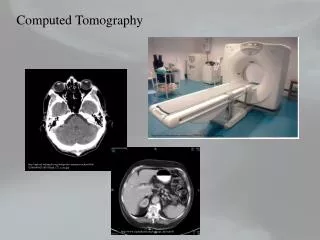
Introduction • 3D distribution of tissue-properties • Density (absorption of X-rays, speed of sound…) • Chemical composition • Temperature • ... • Imaging of these local tissue properties using grayscale or color mapping
Whole Body CT • Good S/N • Good contrast bone/soft tissue • Slice thickness 2-5 mm 2 cm
Peripheral CT • Good Contrast Bone/Soft tissue • Voxelsize 100 mm • Limited FOV (130 mm) 1 cm
Microtomography • Excellent contrast bone/soft tissue • Slice thickness and in plane resolution <10 mm • More noise in images 1 mm
CT-Basics • Based on measurement of attenuation of X-rays (Beer-Lambert): • Measurement of a projection value (Sample): Source Detector m Io I d
Measurement of one projection Io I t t
Projection Value Measurement I I I0 m X-rays Source Object Detector
Source • X-Ray Tubes (most common) • Continuous, steady output (high flux) • Small focal spot (< 10 mm) • Variable energy and intensity • Polychromatic beam I E
Attenuation coefficient m [1/cm] • Attenuation coefficient changes with material: • Attenuation coefficient changes with energy: m bonemusclefat E
I I E E Beam Hardening • Soft X-rays are attenuated more than hard X-rays • Depending on object, spectrum changes m(E) d
Detectors • Usually detect visible light only • Counting Systems (Photomultipliers) • Integrating Systems (CCD, Diode Arrays, CMOS-Detectors) • They all need Scintillators • Convert X-rays into light • NaI, CsI, CdTe ... • The thicker, the more efficient, but the thiner, the better the spatial resolution (tradeoff between high output or high res) • Fiber optics (straight or tapered) in between to protect from remaining X-rays
CT-Measurement • For a CT measurement one needs an certain number of single projection measurements at different angles (theoretically, an unlimited number is required) • In realized Tomography-Systems one usually finds a geometrically ordered detector configuration
1st generation scanner • Single Detector System • Translation-Rotation • 5 min. per slice
2nd generation scanner • multichannel-Systems (4, 6, 8, 16) • Translation-Rotation • 20 sec. per slice
3rd generation scanner • Fan-Beam-Geometry • multichannel-system (500+ detectors), angle > 180o • Rotation of tube and detektorsystem • no translation • 1 – 10 sec. per slice
Parallel Beam (Synchrotron) • Parallelbeam • Rotation of object only • No collimators required • 2D-Detector arrays A. Kohlbrenner, ETH Zürich
Cone Beam • Tube with focal spot • Linear, 2-D Detector (e.g. 1024 x 1024 Elements, CCD) • Single rotation • Artefacts due to improper scanning scheme (would require to different movements) A. Kohlbrenner, ETH Zürich
Spiral scanning • Continuous movement of patient during rotation • Volumetric measurement • Slicewise reconstruction with variable slice thickness by interpolation • As scanner can continuously rotate, one can achieve much faster scan speeds • Latest models (clinical scanners) with parallel detector rings (Multirow, currently up to 64) • 40 slices per second (150 rpm) • No need in current MicroCT systems as the rotation speed is low
Reconstruction • Iterative reconstruction • ART (Arithmetic Reconstruction Technique) • Assume image (base image) • Calculate projections of this base image • Modify image after comparing calculated projections with measured Projections • Strategy...
Reconstruction • Direct method: The measured projections are backprojected under the same angle as the measurement was taken. All projections are summed up
Artefacts • Beam Hardening • Attenuation coefficients depend on energy • soft X-rays are much more absorbed than harder X-rays • Distribution changes when beams penetrate object • Segmentation problems
Artefacts • Object outside of FOV • Inconsistent set of projection data (only partially within the beam at some angles, completely in the beam at other angles) • Local Reconstruction: only for geometry
Artefacts • Motion • Object moves during scan • May be eliminated by external gating (respiratory, heart beat) • Total absorption of X-Rays e.g. Caused by metallic implants (division by 0 in reconstruction) • Other Artefacts • Wrong geometry (fan-beam-angle) • Centers artefact • Mechanical alignment • Insufficient no. of projections (sampling) • ...
Resources • Volume of 1024 x 1024 x 1200 requires 2.4 GB (short integer) • Doubling the resolution requiers 8x more time to calculate • Doubling the resolution requiers 8x more disk space