Download
1 / 21
210 likes | 212 Views
This project aims to integrate the EPS and ADCS subsystems on a single module of the CubeSat standard, reducing overall cost, weight, and power consumption. Commercial off-the-shelf components are selected based on power loss analysis, with a focus on miniaturization and weight reduction. The CubePMT, an 8-layer PCB, includes electronic subsystems, solar panels, and a magnetorquer coil. The EPS incorporates a power boost converter and MPPT for efficient operation of the solar panel, while the ADCS includes a magnetometer sensor and an attitude control system. The goal is to increase efficiency, reduce size and power consumption, and meet orientation and stabilization requirements.

E N D
Engineering of Power Management Tile and Attitude Control for 3U ARAMIS Candidate: Zohaib Aziz 219599 Tutor: Prof. Leonardo M. Reyneri
Problem Statment • Integration of EPS(Electric Power Supply) & ADCS (Attitiude Determiation and Control System)on a single module of CubeSat standard • Reduce the overall cost, weight and power consumption • EPS should meet the power requirement of CubePMT • ADCS should meet orientation and stabilization requirement of 3U AraMiS-C1 • COTS(Commercial of the Shelf) • Selected on the basis of power loss analysis • Small dimensions, compact, Low price and easily available • Techniques for miniturization and weight reduction • Embedded complex maqnetorquer coil in internal layers of the CubePMT
Outline • CubePMT • Block Diagram of 3U Aramis • CubePMT Subsystem • EPS Blocks • ADCS Blocks • 3D View of 1B8_CubePMT_3U AraMiS • Conclusion
CubePMT • CubePMT is CubeSat standard Power Management Tile • Dimensions 324.9 x 82.5 mm2 & 1.6 mm thickness • It is an 8-layers PCB • On top layer : electronic of EPS and ADCS subsystems • Bottom layer : Solar panel and sun sensor • Magnetorquer coil embedded in four internal layers • The target environment for AraMiS satellites is the Low Earth Orbit (LEO) with an expected operation life of 5 years. • Goals • Implement all the subsystems on a single Module • Increase efficiency of EPS • Reduce the overall cost, weight, size and power consumption • COTS
EPS: Solar Panel • Composed of two hexa junction GaAs solar cells • Efficiency of 26% • Each cell generates 2.14V • Connected in series • voltage 13.2V • Single solar cell P-V characteristics at two different temperatures (25˚C & 45˚C) • As the temperature increase performance degrades in terms of • Output voltage • Power
Boost Converter: Simulations • Converts the Solar Panel voltage to PDB level • Solar panel MPP is not constant varies with environment conditions • To operate solar panel at MPP, MPPT is needed • MPPT extracts maximum power from solar panel • Different components were analyzed in LT-Spice simulations • Best selected on basis of minimum losses and small dimensions
Implemented Boost Converter • After good simulation results with the selected components, the converter was implemented • Operation of the MPPT • Input capacitor is charged from solar cells • When voltage on (IN+) of OPAM • is greater than ref (IN-) terminal
Regulators • PDB voltage to low levels(3V, 3.3V, 5V) • Linear regulator (small area & less auxiliary components but low efficiency) • 3V Reference: 5V input to 3V • 3.3V Processor Supply: PDB voltage to 3.3V(only for processor) • Switching regulator (high efficiency, large dimensions & more auxiliary components) • PDB voltage level to 3.3V (all the subsystem components) • PDB voltage level to 5V (all the subsystem components)
ADS: Magnetometer Sensor • A sensor that measures the earth magnetic field for the determination of attitude parameter is known as Magnetometer. • Magnetometer are extensively used • low-price, lightweight and low power consumption • Types of magnetic sensor technologies available • FG (Fluxgates): Good magnetic properties but heavier (500mg), consume high power (2W), expensive • GMR (Giant Magneto Resistance): Good sensing properties and repeatability but high hysteresis (up to 10%) and low magnetic field sensing is not trivial • TMR (Tunnel Magneto Resistance): Good sensitivities, high magnetic field range and good resolution. But TMR is immature technology, COTS are not very widely spread • AMR (Anisotropic Magneto Resistance): High dynamic ranges (hundred of µT), high resolution (1nT), higher sensitivities (10mV/mT/Vbridge ) and Set/Reset pulses • CubePMT: COTS Honeywell HMC1002 • AMR technology • Two-axis sensors • Measurement range: -2~2 G • Maximum earth magnetic field -0.625~0.625 G
ADS: Magnetometer Sensor • Set/reset pulses • Refresh the sensor • Maintain sensitivity • Eliminate memory effects of the magnetic elements • Magnetometer • Conditional circuit • Output voltage in range of tile processor (0V~2.5V).
FIELD (0, 1) FIELD (1, 0) ADS: Magnetometer Sensor FIELD (0, 1) FIELD (1, 0) FIELD (0, 0) FIELD (1, 1)
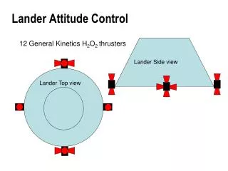
Attitude Control System (ACS) • Manages satellite orientation, in order to point its antenna toward ground station or solar panels toward sun. • Choices • Permanent magnets • Cheap, simple, light and consuming no power • Problem pointing accuracy and pointing direction • Reaction wheels • better pointing accuracy and can orientate satellite in any direction • Price, weight and size make them incompatible with CubePMT • Magnetic rods • better pointing accuracy and can orientate satellite in any direction • Price, weight and size make them incompatible with CubePMT • Magnetorquer system • Magnetorquer Coil Driver • Magnetorquer Coil
ACS: Magnetorquer Coil • Working Principle • When current flows through a solenoid, magnetic moment is generated • Current carrying coil is placed in a magnetic field, it generates a torque • In case of LEO, at an altitude of 800 km and inclination angle of 89°, varies between 0.15G and 0.45G
ACS: Magnetorquer Coil • Design requirements • Small dimensions • Low weight • Low heat dissipation • Reconfigurable • Occupying no excess space • Can generate different amount of magnetic moment and torque
ACS: Magnetorquer Coil • Design parameters • Embedded in four internal layers • 30 turns in each layer • 120 turns total • Trace width 0.3mm and thickness of 18µm • Space between adjacent traces is 0.2mm
Magnetorquer Coil Design Magnetic Moment VS 50 turns of Coil and Magnetic Moment/Power Consumption Magnetic Moment VS 30 turns of Coil and Magnetic Moment/Power Consumption
Conclusion • All the subsystem on a single module • COTS, more compact and rigid system, resulted in low cost • Weight around 200g • EPS • Selected on basis of power loss analysis & minimum dimensions • Meet the power requirement of 3U 1B8_CubePMT • Magnetorquer Coil • No excess space, reconfigurable • Any combination of coils, different magnetic moment, low power dissipation and heat generation • Almost weightless