Download
1 / 31
310 likes | 450 Views
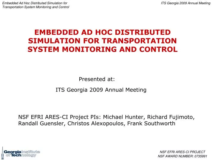
NSF EFRI ARES-CI Project PIs: Michael Hunter, Richard Fujimoto, Randall Guensler, Christos Alexopoulos, Frank Southworth. Presented at:. ITS Georgia 2009 Annual Meeting. EMBEDDED AD HOC DISTRIBUTED SIMULATION FOR TRANSPORTATION SYSTEM MONITORING AND CONTROL.

E N D
NSF EFRI ARES-CI Project PIs: Michael Hunter, Richard Fujimoto, Randall Guensler, Christos Alexopoulos, Frank Southworth Presented at: ITS Georgia 2009 Annual Meeting EMBEDDED AD HOC DISTRIBUTED SIMULATION FOR TRANSPORTATION SYSTEM MONITORING AND CONTROL
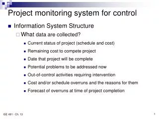
OBJECTIVE - Reconfigurable, resilient, transportation system monitoring, forecasting & control Research Overview
Dedicated Short Range Communications (DSRC) • 5.850-5.925 GHz • V2V, V2R communication • 802.11p protocol • 7 channels, dedicated safety channel • 6- 27 Mbps • Up to 1000 m range U.S. DOT IntelliDrivesm • Provide connectivity among roadway users and the roadside • Improve safety, mobility, and environment Current Trends Smart Vehicles • On-board GPS, digital maps • Vehicle, environment sensors • Significant computation, storage, communication capability • Not power constrained
WWAN BS WLAN AP WLAN AP Region Wide Traffic Network IN-VEHILCE SIMULATION IN-VEHILCE SIMULATION Vehicle-to-Vehicle and Vehicle-to-Roadside Communication Architecture to Central Server IN-VEHILCE SIMULATION Traffic Control Adjustments Data Requests In-Vehicle Simulation Predictions IN-VEHICLE SIMULATION Traffic Sensors REGIONAL SERVER In-Vehicle Data Module Historical Data Physical Data - - Area wide traffic projection In-Vehicle Simulation REGIONAL DISTRIBUTED SIMULATION - - Wide area control adjustments Control Updates Traffic Control - - Redirect mobile sensor - - Adjust sensor polling
Ad Hoc Distributed Simulation Roadside-to-vehicle communication Instrumented traffic signal controller Vehicle-to-Vehicle communication In-Vehicle Simulations
IN-VEHICLE SIMULATION IN-VEHICLE SIMULATION IN-VEHICLE SIMULATION Individual Vehicles Simulate Local Area of Interest IN-VEHICLE SIMULATION Ad Hoc Distributed Simulations • An Ad Hoc distributed simulation is a composition of autonomous on-line simulators, each modeling its own “area of interest” independent of other simulators • Simulators may be stationary or mobile • Area of interest may vary over time • Not a clean partitioning of physical system • Areas modeled by different simulators may overlap • Some areas may not be modeled at all • Sensor network captures current system state • Simulation used to project future system states • Simulation-based system optimization
Processor2 Processor1 Processor4 Processor3 Conventional vs. Ad Hoc Conventional • Top-Down construction • Clean partition of state space; static partition • Produce same results as a single run Ad Hoc • Bottom-Up construction • Ad Hoc partition of state space; dynamic partition • Produce same statistical results as replicated runs
State Prediction Questions State prediction problems: • Can a collection of localized simulations provide accurate predictions of the overall system state? • Static prediction: Given a current snapshot of the state of the system, what is the predicted, future state? • Dynamic predication: Given a new snapshot of the state of the system, what is the (revised) prediction of future system state?
In-Vehicle Simulations Execution Mechanism Space-Time memory • System state: Space-Time Memory • Time stamp addressed memory • Stores current and predicted system state • Autonomous simulators • Read current, predicted state from STM • Compute future state predictions • Provide updates to STM • Optimistic synchronization (Rollback) • Prediction errors arise when • Sensor readings do not match predictions • Predictions from other simulators change • If error sufficiently large, roll back simulator and re-compute new projection Roadside Server (other levels of hierarchy, e.g., regional, traffic management center not shown)
Synchronization • Simulators predict future state of system based on on-line measurement • These predictions may be wrong due to unexpected events (e.g., accidents) • If prediction does not match measured state, roll back simulation, and re-compute new future state based on measured data • If new predicted state very different from previously projected state, may trigger additional rollbacks (cascaded rollbacks)
200vph Passing upstream traffic state to downstream • Non-congested condition • Vehicle 1 detects volume decrease at 7:10PM • Vehicle 1 runs simulation & predicts volume on Link A will reach 270vph at 7:22PM • Server compares the data. Difference between 500vph & 270vph exceeds 200vph threshold • Server sends rollback message to Vehicle 2 saying new flow rate is 270vph at 7:22PM • Vehicle 2 resumes its simulation with updated info Vehicle 2 Link j Vehicle 1
Congested condition Average traffic flow: 500vph / Average speed 48km/hr Incident at 7:10PM & speed drops to 2km/hr for 15min (Queue toward upstream) Vehicle 2 detects the incident. This info needs to be delivered to vehicle 1 Vehicle 1 needs to represent this congested traffic condition Reduce speed of vehicles on link A in its simulation to create congested condition Vehicle 1 Reduce speed to create queue Passing downstream traffic state to upstream Incident Link j Queue Vehicle 2 Vehicle 1
Passing downstream traffic state to upstream • Vehicle 2 detects incident at 7:10PM • Vehicle 2 runs simulation predicting speed on Link A will reach 2kmph at 7:20PM • Sends prediction to server • Server sends rollback message to Vehicle 1 • Vehicle1 is rollbacked to 7:20PM with new data Incident Link j Queue Vehicle 2 Vehicle 1
Automated Update using Rollback Measure increase in traffic flow at A Rollback, re-compute flow at B Roll back simulator when • Prediction and measurement disagree • Predictions from other simulators change A C D flow rate flow rate time time Rollback based on B, re-compute flow at C Rollback based on C, re-compute flow at D flow rate flow rate B time time
Prototype Implementation • Simulators • Custom traffic simulator • Cellular automata • Custom designed for ad hoc execution mechanism • Simplified models • Commercial simulator • VISSIM • Detailed, “industrial strength” microscopic traffic simulator
Cellular Automata Simulator • Vehicle rules • Acceleration • Deceleration • Randomized speed change • Car motion • Straight, turn probabilities • Signal timing • Cycle • Left turn phase • State: vehicle flow rate
Initial Test Network • Test Configuration • 20 in-vehicle simulators, each simulates half of the network • 1 server (space-time memory) • Intel Xeon processors (2.0 to 3.2 GHz), 1 GB memory, running Redhat Enterprise Linux 4 OS, 2.6.9-22.0.1 kernel; LAN interconnect • Test scenarios • Steady state under three demand scenarios • Sudden influx of eastbound traffic at western most link • Clients 1-10 roll back due to sensor data • Clients 11-20 roll back due to change in predictions of clients 1-10 • Compare ad hoc distributed simulation against replicated simulation experiment of entire network
500 veh/hr Predicted Flow Rate - link 10 300 veh/hr 100 veh/hr Simulation time Steady State, Exit Link • Constant input rate at edge of network throughout experiment • Measure flow rate on rightmost link at edge of network • Compare average (replicated trial), client average, single client
Increase Demand • Cellular automata microscopic traffic simulator; single road w/ cross traffic • Initial input rate of 100 veh/hr; at time 1000, increase to 500 veh/hr • Clients 11-20 roll back when change occurs • If the simulators not coupled, clients 11-20 would not predict increase in flow until higher traffic volume reached link 5 Link 0 Link 5 Predicted Flow Rate Link 10 Simulation time
Grid Network Test • Network • Manhattan-style 10 x 10 grid - 100 equally spaced intersections (1320 ft. apart) • Two-lane, two-way roads • Each intersection contains a shared through/right turn lane and a left turn bay. • All intersections operate under a fixed-time, 4 phase, 120 sec cycle • Constant turn rates at each intersection - 85% through, 5% left, 10% right • Main arterials are defined with a higher volume at the horizontal and vertical midpoints of the network • Experiment • Forty clients are distributed over the network • Each simulating a maximum 5 x 3 intersection grid in front of vehicle • Arrival rate on all boundary input roads initialized to a specified value. • Model network under steady state and demand increase conditions • Improved algorithms
Commercial Simulator • Commercial simulator: VISSIM • Scenario: evacuation of Georgia Tech campus • Normal traffic demand at points A-J • Traffic at point A increases from 100 to 600 veh/hr 1800 seconds into scenario • Indicated link is bottleneck (highway overpass) Study Area
Traffic Flow (Overpass) • Simulation emulates the “real world,” provides data to in-vehicle (ad hoc) simulator • Ad hoc simulation predictions at bottleneck link compared to “real world” data
Point Sensors: loop detectors and video cameras Server: polls and processes data from point sensor TS*: subscribes to Server; provides real-time simulated, mirror image of roadway’s current condition TS-1, TS-2, TS-3: client simulations that provide possible future roadway conditions Conceptual Framework* * Henclewood, D., M. Hunter, R. Fujimoto. Proposed Methodology For A Data Driven Simulation For Estimating Performance Measures Along Signalized Arterials In Real-Time, Proceedings of the 2008 Winter Simulation Conference, Miami, Florida, 2008.
Experimental Design • 3 intersection network under semi-actuated control • 8 boundary detection points • Volume 1200 to 550 vehicle/hr • Named-Pipe used for communication between VISSIM instances, with the aid of VISSIM’s COM module and C++ • Detectors model under perfect detection - ID - and realistic - RD - (i.e., 10% speed error, 2% loss) Pipe-server Pipe-Client 29
Results • General Observations • In-vehicle Simulation appears capable of accurately reflecting real-world • However, instances are seen where real-world not consistently tracked, particularly during peak flow • Next Steps • Explore the impacts of VISSIM’s Calibration parameters – “perfect” calibration • Identify, quantify, and address factors that caused significant variation noted during the peak demand period • Incorporate detector data from internal detectors • Incorporate probe data • Allow for changing roadway topology to reflect vehicle movement 30
Questions and Discussion Contact Information – michael.hunter@ce.gatech.edu (404) 385-1243