Download
1 / 28
280 likes | 412 Views
University of Nevada – Reno Computer Science & Engineering Department Fall 2011 CPE 400 / 600 Computer Communication Networks. Lecture 17 Network Layer (Virtual Circuits, Datagrams, Routers). slides are modified from J. Kurose & K. Ross. 4. 1 Introduction

E N D
University of Nevada – Reno Computer Science & Engineering Department Fall 2011 CPE 400 / 600Computer Communication Networks Lecture 17 Network Layer (Virtual Circuits, Datagrams, Routers) slides are modified from J. Kurose & K. Ross Introduction
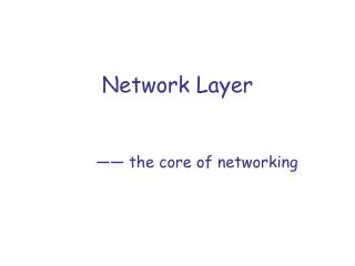
4. 1 Introduction 4.2 Virtual circuit and datagram networks 4.3 What’s inside a router 4.4 IP: Internet Protocol Datagram format IPv4 addressing ICMP IPv6 4.5 Routing algorithms Link state Distance Vector Hierarchical routing 4.6 Routing in the Internet RIP OSPF BGP 4.7 Broadcast and multicast routing Chapter 4: Network Layer Network Layer
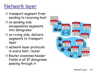
Network layer connection and connection-less service • datagram network provides network-layer connectionless service • VC network provides network-layer connection service • analogous to the transport-layer services, but: • service: host-to-host • no choice: network provides one or the other • implementation: in network core Network Layer
call setup, teardown for each call before data can flow each packet carries VC identifier not destination host address every router on source-dest path maintains “state” for each passing connection link, router resources (bandwidth, buffers) may be allocated to VC dedicated resources = predictable service “source-to-dest path behaves much like telephone circuit” performance-wise network actions along source-to-dest path Virtual circuits Network Layer
VC implementation a VC consists of: • path from source to destination • VC numbers, one number for each link along path • entries in forwarding tables in routers along path • packet belonging to VC carries VC number • rather than destaddress • VC number can be changed on each link. • New VC number comes from forwarding table Network Layer
VC number 22 32 12 3 1 2 interface number Forwarding table Forwarding table in northwest router: Incoming interface Incoming VC # Outgoing interface Outgoing VC # 1 12 3 22 2 63 1 18 3 7 2 17 1 97 3 87 … … … … Routers maintain connection state information! Network Layer
used to setup, maintain teardown VC used in ATM, frame-relay, X.25 not used in today’s Internet application transport network data link physical application transport network data link physical Virtual circuits: signaling protocols 6. Receive data 5. Data flow begins 4. Call connected 3. Accept call 1. Initiate call 2. incoming call Network Layer
no call setup at network layer routers: no state about end-to-end connections no network-level concept of “connection” packets forwarded using destination host address packets between same source-dest pair may take different paths application transport network data link physical application transport network data link physical Datagram networks 1. Send data 2. Receive data Network Layer
Forwarding table 4 billion possible entries Destination Address RangeLink Interface 11001000 00010111 00010000 00000000 through 0 11001000 00010111 00010111 11111111 11001000 00010111 00011000 00000000 through 1 11001000 00010111 00011000 11111111 11001000 00010111 00011001 00000000 through 2 11001000 00010111 00011111 11111111 otherwise 3 Network Layer
Longest prefix matching Prefix MatchLink Interface 11001000 00010111 00010 0 11001000 00010111 00011000 1 11001000 00010111 00011 2 otherwise 3 Examples Which interface? DA: 11001000 00010111 00010110 10100001 Which interface? DA: 11001000 00010111 00011000 10101010 Network Layer
Internet (datagram) data exchange among computers “elastic” service, no strict timing req. “smart” end systems (computers) can adapt, perform control, error recovery simple inside network, complexity at “edge” many link types different characteristics uniform service difficult ATM (VC) evolved from telephony human conversation: strict timing, reliability requirements need for guaranteed service “dumb” end systems telephones complexity inside network Datagram or VC network: why? Network Layer
4. 1 Introduction 4.2 Virtual circuit and datagram networks 4.3 What’s inside a router 4.4 IP: Internet Protocol Datagram format IPv4 addressing ICMP IPv6 4.5 Routing algorithms Link state Distance Vector Hierarchical routing 4.6 Routing in the Internet RIP OSPF BGP 4.7 Broadcast and multicast routing Chapter 4: Network Layer Network Layer
Router Architecture Overview Two key router functions: • run routing algorithms/protocol (RIP, OSPF, BGP) • forwarding datagrams from incoming to outgoing link Network Layer
Input Port Functions Decentralized switching: • given datagram dest., lookup output port using forwarding table in input port memory • goal: complete input port processing at ‘line speed’’ • queuing: if datagrams arrive faster than forwarding rate into switch fabric Physical layer: bit-level reception Data link layer: e.g., Ethernet see chapter 5 Network Layer
Three types of switching fabrics Network Layer
Memory Input Port Output Port System Bus Switching Via Memory First generation routers: • traditional computers with switching under direct control of CPU • packet copied to system’s memory • speed limited by memory bandwidth • 2 bus crossings per datagram Network Layer
Switching Via a Bus • datagram from input port memory to output port memory via a shared bus • bus contention: switching speed limited by bus bandwidth • 32 Gbps bus, Cisco 5600: • sufficient speed for access and enterprise routers Network Layer
Switching Via An Interconnection Network • overcome bus bandwidth limitations • Banyan networks • other interconnection nets initially developed to connect processors in multiprocessor • advanced design: • fragmenting datagram into fixed length cells • switch cells through the fabric. • Cisco 12000: switches 60 Gbps through the interconnection network Network Layer
Output Ports • Buffering required when datagrams arrive from fabric faster than the transmission rate • Scheduling discipline chooses among queued datagrams for transmission Network Layer
Output port queueing • buffering when arrival rate via switch exceeds output line speed • queueing (delay) and loss due to output port buffer overflow! Network Layer
. RTT C N How much buffering? • RFC 3439 rule of thumb: average buffering equal to “typical” RTT (say 250 msec) times link capacity C • e.g., C = 10 Gps link: 2.5 Gbitbuffer • Recent recommendation: with N flows, buffering equal to Network Layer
Input Port Queuing • Fabric slower than input ports combined -> queueing may occur at input queues • queueing delay and loss due to input buffer overflow! • Head-of-the-Line (HOL) blocking: • queued datagram at front of queue prevents others in queue from moving forward Network Layer
4. 1 Introduction 4.2 Virtual circuit and datagram networks 4.3 What’s inside a router 4.4 IP: Internet Protocol Datagram format IPv4 addressing ICMP IPv6 4.5 Routing algorithms Link state Distance Vector Hierarchical routing 4.6 Routing in the Internet RIP OSPF BGP 4.7 Broadcast and multicast routing Chapter 4: Network Layer Network Layer
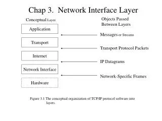
Host, router network layer functions: • ICMP protocol • error reporting • router “signaling” • IP protocol • addressing conventions • datagram format • packet handling conventions • Routing protocols • path selection • RIP, OSPF, BGP forwarding table The Internet Network layer Transport layer: TCP, UDP Network layer Link layer physical layer Network Layer
4. 1 Introduction 4.2 Virtual circuit and datagram networks 4.3 What’s inside a router 4.4 IP: Internet Protocol Datagram format IPv4 addressing ICMP IPv6 4.5 Routing algorithms Link state Distance Vector Hierarchical routing 4.6 Routing in the Internet RIP OSPF BGP 4.7 Broadcast and multicast routing Chapter 4: Network Layer Network Layer
IP datagram format IP protocol version number 32 bits total datagram length (bytes) header length (bytes) type of service head. len ver length for fragmentation/ reassembly fragment offset flgs 16-bit identifier max number remaining hops (decremented at each router) upper layer time to live header checksum 32 bit source IP address 32 bit destination IP address upper layer protocol to deliver payload to E.g. timestamp, record route taken, specify list of routers to visit. Options (if any) data (variable length, typically a TCP or UDP segment) how much overhead with TCP? 20 bytes of TCP 20 bytes of IP = 40 bytes + app layer overhead Network Layer
network links have MTU (max.transfer size) - largest possible link-level frame. different link types, different MTUs large IP datagram divided (“fragmented”) within net one datagram becomes several datagrams “reassembled” only at final destination IP header bits used to identify, order related fragments IP Fragmentation & Reassembly fragmentation: in: one large datagram out: 3 smaller datagrams reassembly Network Layer
length =1500 length =1040 length =1500 length =4000 ID =x ID =x ID =x ID =x fragflag =0 fragflag =0 fragflag =1 fragflag =1 offset =0 offset =185 offset =0 offset =370 IP Fragmentation and Reassembly Example • 4,000 byte datagram • MTU = 1,500 bytes One large datagram becomes several smaller datagrams 1480 bytes in data field offset = 1480/8 Network Layer