Download

1 / 72
720 likes | 949 Views
Color Image Processing. CS 663, Ajit Rajwade. Pouring in color. Grayscale image: 2D array of size M x N containing scalar intensity values ( graylevels ).

E N D
Color Image Processing CS 663, AjitRajwade
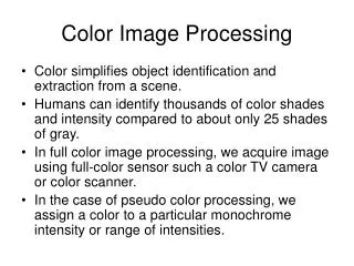
Pouring in color • Grayscale image: 2D array of size M x N containing scalar intensity values (graylevels). • Color image: typically represented as a 3D array of size M x N x 3 again containing scalar values. But each pixel location now has three values – called as R(red),G(green), B(blue) intensity values. • All file formats store color images based on this representation.
Questions • What are RGB? How are red, green, blue determined? • Are there other ways of representing color? • How do you distinguish between different intensities of the same color (shades)? Between varying levels of whiteness in a color (tints)?
More questions • How would you define an edge in a color image? • How do you smooth color images? • What are the advantages of color images over grayscale images? • What do we know about human color perception? • What do color-based optical illusions teach us? • Why do we consider only 3 channels (i.e. RGB)? Are there images with more channels? Where are they used?
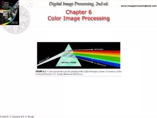
Color perception and physics • Human perception of color is not fully understood, but there are some well understood physical principles. • The color of light is defined by its constituent wavelengths (inverse of frequency). • The visible part of the electromagnetic spectrum lies between 450 nm (violet) to 700 nm (red).
Infrared Ultraviolet
Color physics • White light is a blend of several wavelengths of light, which get separated by “dispersive elements” such as prisms. • Objects which reflect light that is balanced in several visible wavelengths appear “white”. • Objects which reflect light in a narrow range of wavelengths appear “colored” (example: green objects reflect light between 500 to 560 nm). • No color starts or ends abruptly at a particular wavelength – the transitions are smooth.
Human color perception • The human retina has two types of receptor cells that respond to light – the rods and the cones. • The rods work in the low-light regime and are responsible for monochromatic vision. • The cones respond to brighter light, and are responsible for color perception. • There are around 5-7 million cones in a single retina.
Human color perception • There are 3 types of cones. Each type responds differently to light of different wavelengths: L (responsive to long wavelengths, i.e. red), M (medium wavelengths, i.e. green) and S (short wavelengths, i.e. blue). Yellow color: L is stimulated a bit more than M and S is not stimulated Red: L is stimulated much more than M and S is not stimulated Violet: S is stimulated, M and L are not Color-blindness: absence of one or more of the three types of cones Response sensitivity functions for LMS cells
Human color perception • Consider a beam of light striking the retina. Let its spectral intensity as a function of wavelength λ be given as I(λ). • The three types of cone cells re-weigh the spectral intensity and produce the following response: C is a matrix of size 3 x Nλ and I is a vector of Nλ elements Vectors of length Nλ
Human color perception • The colors R,G,B are called primary colors – their corresponding wavelengths are 435, 546, 700 nm respectively. • These values were standardized by CIE (International Commission on Illumination – Commission Internationale de l’Eclairage).
Display systems (CRT/LCD) • The interior of a cathode ray tube (CRT) contains an array of triangular dot patterns (triads) containing electron-sensitive phosphor. Each dot in the triad produces light in one of the three primary colors based on the intensity of that primary color. • Thus the three primary colors gets mixed in different proportions by the color sensitive cones of the human eye to perceive different colors. • Though the electronics of an LCD system is different from CRT, the color display follows similar principles.
Color Models (Color Spaces) • A purpose of color model is to serve as a method of representing color. • Some color models are oriented towards hardware (eg: monitors, printers), others for applications involving color manipulation. • Monitors: RGB, Printers: CMY, humanperception: HSI, efficient compression and transmission: YCbCr.
RGB color model • Defines a cartesian coordinate system for colors – in terms of R,G,B axes. • Images in the RGB color model consist of three component images, one for each primary color. • When an RGB image is given as input to a display system, the three images combine to produce the composite image on screen. • Typically, an 8 bit integer is used to represent the intensity value in each channel, giving rise to (2^8)^3 = 1.677 x 10^7 colors.
CMY(K) color space • The colors cyan, magenta and yellow are “opponents” of red, green and blue respectively, i.e. cyan and red lie on diagonally opposite corners of the RGB cube, i.e. • C = 255-R, M = 255-G, Y = 255-B • Cyan, magenta and yellow are called secondary colors of light, or primary colors of pigments. A cyan colored surface illuminated with white light will not allow the reflection of red light. Likewise for magneta and green, yellow and blue. • CMY are the colors of ink pigments used in printing industry. Color printing is a subtractive process – the ink subtracts certain color components from white light. • For purposes of display, white is the full combination of RGB and black is the absence of light. For purposes of printing, white is the absence of any printing, and black is the full combination of CMY. See also: http://home.comcast.net/~rtruscio/colorsys.htm
CMY(K) color space • The printer puts down dots (of different sizes, shapes) of CMY colors with tiny spacing (of different widths) in between. The spacing is so tiny that our eye perceives them as a single solid color (optical illusion!). This process is called color half-toning. • While black is a full combination of CMY, it is printed on paper using a separate black-color ink (to save costs). This is the ‘K’ of the CMYK model.
Color half-toning http://en.wikipedia.org/wiki/Halftone Three examples of color half-toning with CMYK separations. From left to right: The cyan separation, the magenta separation, the yellow separation, the black separation, the combined halftone pattern and finally how the human eye would observe the combined halftone pattern from a sufficient distance.
Digression: Gray-scale half-toning http://en.wikipedia.org/wiki/Halftone Left: Halftone dots. Right: How the human eye would see this sort of arrangement from a sufficient distance.
Digression: negative after-images! http://thebrain.mcgill.ca/flash/a/a_02/a_02_p/a_02_p_vis/a_02_p_vis.html#
HSI color space • RGB, CMY are not intuitive from the point of view of human perception/description. • We don’t think naturally of colors in the form of combinations of RGB. • We tend of think of color as the following components: hue (the “inherent/pure” color – red, orange, purple, etc.), saturation (the amount of white mixed in the color, i.e. pink versus magenta), intensity (the amount of black mixed in the color, i.e. dark red versus bright red).
Intensity increases as we move from black to white on the intensity line. • Consider a plane perpendicular to the intensity line (in 3D). Saturation of a color increases as we move on that plane away from the point where the plane and the intensity line intersect. • How to determine hue? Pick any point (e.g. yellow) in the RGB cube, and draw a triangle connecting that point with the white point and black point. All points inside or on this triangle have the same hue. Any such point would be a color corresponding to a convex combination of yellow, black and white, i.e. of the form • a x yellow + b x black + c x red, where a, b, c are non-negative and sum to 1. By rotating this triangle about the intensity axis, you will get different hues.
HSI space By rotating the triangle about the intensity axis, you will get different hues. In fact hue is an ANGULAR quantity ranging from 0 to 360 degrees. By convention, red is considered 0 degrees. Primary colors are separated by 120 degrees. The secondary colors (of light) are 60 degrees away from the primary colors.
To be very accurate, this HSI spindle is actually hexagonal. But it is approximated as a circular spindle for convenience. This approximation does not alter the notion of hue or intensity and has an insignificant effect on the saturation.
RGB to HSI conversion • Conversion formulae are obtained by making the preceding geometric intuition more precise: Refer to textbook for formulae to convert back from HSI to RGB
Practical use of hue • Hue is invariant to: • Scaling of R,G,B • Constant offsets added to R,G,B • What does this mean physically?
Practical use of hue • To understand this, we need to understand a model which tells you the what color is observed at a particular point on a surface of an object illuminated by one or more light sources. • This color is given by: Diffuse reflection of light from a directed source off a rough surfaces: varies from point to point on a surface Reflection from shiny surface: varies from point to point on a surface Ambient light (say due to sunlight): constant effect on all points of the object’s surface
Diffuse reflection from an irregular surface Specular reflection
Diffuse reflection from a rough surface: “diffuse” means that incident light is reflected in all directions. • Specular reflection: part of the surface acts like a mirror, the incident light is reflected only in particular directions Diffuse reflection Diffuse + specular reflection L=Strength of white light source, ka,kd,ks: surface reflectivity (fraction of incident light that is reflected off the surface) Vector normal to the surface at a point Lighting direction Viewing direction Direction of reflected light For shiny surfaces, α is large.
Practical use of hue • The ambient and specular components are assumed to be the same across RGB (neutral reflection model). So they get subtracted out when computing R-G,G-B,B-R. Hence hue is invariant to specular reflection! • Notice: hue is independent of strength of lighting (why?), lighting direction (why?) and viewing direction (why?). • This makes hue useful in object detection and object recognition or in applications such as detection of faces/foliage in color images. • Hue is thus said to be an “illumination invariant” feature.
Food for thought • We’ve heaped praises on hue, all along. Any ideas on its demerits? • Suppose we define the following quantities (r,g,b) [the chromaticity vector] derived from RGB: Is the chromaticity vector also an illumination invariant feature? How does it compare to hue?
Digression: Playing with color: seeing is not (!) believing http://thebrain.mcgill.ca/flash/a/a_02/a_02_p/a_02_p_vis/a_02_p_vis.html# http://en.wikipedia.org/wiki/Optical_illusion
Operations on color images • Color image histogram equalization • Color image filtering • Color edge detection
Histogram equalization • Method 1: perform histogram equalization on RGB channels separately. • Method 2: Convert RGB to HSI, histogram equalize the intensity, convert back to RGB. • Method 1 may cause alterations in the hue – which is undesirable. • Method 2 will change only the intensity, leaving hue and saturation unaltered. It is the preferred method.
Top row: original images Middle row: histogram equalization channel by channel Bottom row: histogram equalization on intensity (of HSI) and conversion back to RGB
Color image smoothing: bilateral filtering • Remember the bilateral filter (HW2): an edge-preserving filter for grayscale images. • It smoothes the image based on local weighted combinations driven by difference between spatial coordinates and intensity values.
Bilateral filtering for color images • You can filter each channel separately, i.e.
Bilateral filtering for color images • Or you can filter the three channels in a coupled fashion, i.e. the smoothing weights are same for all three channels and they are derived using information from all three channels.
Channel by channel: Color artifacts around edges. RGB channels are highly inter-dependent – you shouldn’t treat them as independent. What’s wrong with separate channel bilateral filtering? Separate channel Coupled
Color Edges • A color (RGB) image will have three gradient vectors – one for each channel. • We could compute edges separately for each channel. • Option: Combine (add) channel-per-channel edges together to get a composite edge image. Not a good one? Why (see next slide)
Color Edges • Problem: the two circled points have the same edge strength (mathematically), though one appears to be a stronger edge. (Rx,Gx,Bx) = (255,255,255), (Ry,Gy,By) = (0,0,0), Rx^2 + Gx^2 +Bx^2 + Ry^2+Gy^2+By^2 = 3*255^2 (Rx,Gx,Bx) = (255,255,0), (Ry,Gy,By) = (0,0,255), Rx^2 + Gx^2 +Bx^2 + Ry^2+Gy^2+By^2 = 3*255^2
Color Edge • We want to ask the question: along which direction in XY space is the total magnitude of change in intensity the maximum? • The squared change in intensity in a direction (cosϴ, sin ϴ) is given by (square of the directional derivative of the intensity): • We want to maximize this w.r.tϴ. Take derivative with respect to ϴ and set it to zero.
Color Edge • This gives the color gradient direction which makes an angle ϴw.r.t. the X axis, given by: • For a grayscale image, this turns out to be
Color Edge • Consider • It turns out that the ϴ (i.e. the color gradient) we derived is given by the eigenvector of this matrix corresponding to the larger eigenvalue. The direction perpendicular to it (i.e. the eigenvector corresponding to the smallereigenvalue) is the color edge. Local color gradient matrix