Download

1 / 17
180 likes | 201 Views
10 Important Technical Tests for Troubleshooting the Maxitrol GV60 System. Necessary Tools for Troubleshooting. Leak Tester. Multi-Meter. Manometer. The cost of these tools will be recovered in Time Saved. Technical Troubleshooting Review. Do You Have a Parts Kit?

E N D
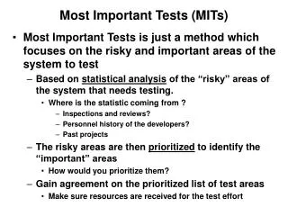
10 Important Technical Testsfor Troubleshooting theMaxitrol GV60 System
Necessary Tools for Troubleshooting Leak Tester Multi-Meter Manometer The cost of these tools will be recovered in Time Saved
Technical Troubleshooting Review Do You Have a Parts Kit? Get the Service Call Finished on the First Visit Special Dealer Price $224.49 (45% off plus additional $50 off) Keep it Stocked! Add Some New Alkaline Batteries
Confirm the Remote & ReceiverAre Communicating Test #1 Does it Say MAN (Manual) on Screen? Does the Battery Icon Show Voltage? Push the Up-Flame – Does the Knob Move? Push the Down-Flame – Does the Knob Move? 1 Beep –No Knob Movement Motor Failure 1 Long Beep Electrical Problem Rapid Beeps For 3-Seconds Low Battery Voltage
Batteries, Batteries, Batteries!! Put Positive Test Probe on Last Pin. Put Negative Test Probe on Ground Test #2 Test Battery Box for Proper Voltage Not Less than 5.8 DCV Corrosion in the Battery Compartment is the #1 Service Issue
Manual Lighting the Fireplace Turn Knob to Manual, Insert Small Tool into Large Hole and Depress. Light Pilot and Hold for 10 sec. Turn back to On Position for Burner Test #3 Do a Manual Light to see if the Fireplace will Light and Gas Supply is Sufficient This Proves that the Thermocouple Circuit is Good
Testing the Thermocouple Circuit Put Positive Test Probe on Red Terminal Put Negative Test Probe on Ground Test #4 Take a MV Reading at the Red Terminal Should have 10 – 15 MV
Testing the Startup Voltage Put Positive Test Probe on Yellow Terminal Put Negative Test Probe on Ground Test #5 Do you hear the “Clunk” When the Solenoid engages? Should read 5+ MV at Yellow as Batteries Power the Magnet
Testing the Voltage Loss in Receiver Put Positive Test Probe on Red Terminal Put Negative Test Probe on Yellow Terminal Test #6 Testing the Voltage Difference Between the Red and Yellow Terminal – No More Than 2-3 MV Loss.
Testing the Gas Valve Dropout Voltage Put Positive Test Probe on Red Terminal Put Negative Test Probe on Ground Test #7A Test Drop Out: Take a MV Reading at the Red Terminal. Shut Off Gas or Blow Pilot Out Should Dropout at about 2 MV
Testing the Gas Valve Dropout Time Alternate Test for Test #7A – Measuring Dropout Voltage Test #7B Shut Off Gas and Measure How Many Seconds Before You Hear the Gas Valve Magnet Reset Less than 10 seconds – BAD More than 20 seconds - GOOD
Direct Vent Window Test Fireplace Burns Right with Window Off Will Not Burn Properly with Window On Test #8 You Have a Vent Problem Remember the Air or Exhaust Restrictors are part of the Vent System
Testing Gas Inlet or House Pressure Test #9 Inlet or House Pressure Test Port Always Test Gas Pressure at Full Flow 5 – 7” NG 11 – 14” LP Remember the Pilot is Running on House Pressure Make Sure You Close the Test Ports and Leak Check
Testing Gas Manifold or Burner Pressure Test #10 Manifold or Burner Pressure Test Port 3.5 – 4” NG 9.5 – 10” LP Always Test Gas Pressure at Full Flow Refer to Data Plate for Correct Manifold Pressure
GV 60 Startup Sequence User Pushes Up Flame and Off Buttons Handset Goes to Manual Mode Motor Moves Valve to Pilot Only Position Motor Ratchets to Prove Micro Switch 5 MV is applied to Gas Valve Magnet (Battery Power) Solenoid Hits Gas Valve Magnet (Clunk) Pilot Gas Starts Flowing Igniter Starts Sparking Pilot Lights and Proves Flame with Thermocouple Relay in Receiver Switches from Batteries to Thermocouple Motor Turns Valve to High Flame
Service Call Goal Let’s Get the Job Done with One Visit! With a Parts Kit The Right Testing Equipment Performing the Right Troubleshooting Tests