Download
1 / 45
450 likes | 541 Views
Ritter Arena Improvements. Joe Cooper Dan Crossen Diego Guinea Alex Peterson Mike Walsh. Projects 1 & 2: Reclaiming Wasted Energy. Dan & Mike. Project 1: Using Wasted Heating for Heating Needs. Daniel Crossen. Current System. 65-90°F. 70-95°F.

E N D
Ritter Arena Improvements Joe Cooper Dan Crossen Diego Guinea Alex Peterson Mike Walsh
Projects 1 & 2: Reclaiming Wasted Energy Dan & Mike
Project 1: Using Wasted Heating for Heating Needs Daniel Crossen
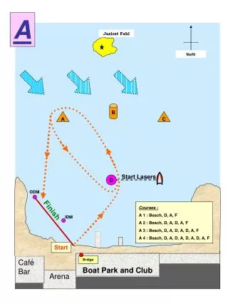
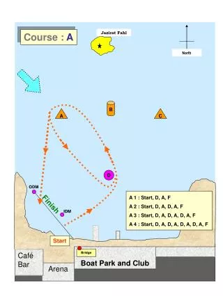
Current System 65-90°F 70-95°F Semi-warm water leaving pumps/entering cooling towers at 70-95° F and leaving cooling towers/entering pumps (for cooling) at 65-90°F Cold water leaving pumps/entering underslab (for warming of ground)at 36° F and leaving underslab/entering pumps at 32°F Currently, these two systems do not interact, other than through the pumps. However, the semi-warm water is only used to cool the pumps, and does not come into contact with the cold water at all.
Current System (cont’d) 65-90°F 70-95°F RIT pays to cool down this water from 65°-90°F to 45°-55°F while… …in the next room, we pay to heat up this water from 32° to 36°F They are on two separate loops, never coming into contact, and energy is wasted moving their temperatures in opposite directions.
System Overview: Using Waste Heat for Heating Take the output of this system (65-90°F) 65-90°F 65-90°F 70-95°F 70-95°F And take the output of this system (32 °F) And put them through a heat exchanger to utilize the waste heat/cold from one system to heat/cool the other system
Project 2: Using Waste Cooling for Air Conditioning Mike Walsh
Customer Feedback • Presented Design to Customer • Customer thought it would be a great idea for savings, but probably impractical unless the savings were immense. • Requires 400+ feet of piping 1-1/4” Lines • Also would require stronger pumps for underslab system. • Not really in the scope of MSD I or II • Perhaps MSD VIII
Arena Schematic Air Handler 3 Air Handler 1 At least 200 feet of piping in each direction Corner Crew Underslab System Air Handler 2 Air Handler 4
Projects 3& 4: Using the Ice Pile Joe & Diego
Project 3: Using the Ice Pile for Air Conditioning Joseph Cooper
Benchmarking • Scaled Goals: • 1/5 size of Ice Bear unit • Similar output to portable a/c unit • Project Goals: • Same output as Ice Bear • Energy usage without freezing ice.
Ice In 0.51 m 0.31m Cool Air Out C 0.25m A B Warm Air In Ice box/container (~1/2 total unit) Air passage/duct w/ heat exchanger (~1/4 total unit) Pump/component area (~1/4 total unit)
Customer Feedback • Customer would like to find purpose for meltwater • Using “Heat Pipes” with a pre charged coil that will migrate depending on the delta-V between cold & hot side. • Is interested in the future possibility of using snow during the winter as well.
Project 4: Using the Ice Pile for Pipe Cooling Diego Guinea
Benchmark Heat Exchanger Flow Rate: 800 GPM Cooling Coil Temperature Sensor Temperature Range: -50oC to 200oC Applicable flow velocity: Less than 4 m/s Time Constant: 50s
Project 5: Monitor and reduce CO emissions in Ritter Arena Alex Peterson
Functional Decomposition Output results and warnings Air Temperature Write data and check against appropriate range Emissions Log File Fan Speed Read all sensors COLevel Make adjustments if needed Fan Speed Parameters Load log and parameter files Check if adjustments happened Emissions Log File Fan Health Check Hardware Availability Check against CO2 required ventilation Sensor Health Hardware log Health Hardware log Health
Customer Feedback • Use handheld detector(s) to measure • Map arena well to find hotspots of emissions • Place sensor in worst part • Interface with controller may be possible if bill of materials and design complete