Download
1 / 47
490 likes | 765 Views
Ignition Systems. Engine Operation. Fuel is burned inside the engine’s combustion chamber to produce heat Heat causes expansion of gases in the engine Expansion in the combustion chamber produces pressure Engine components convert pressure into rotating motion. Engine Operation.

E N D
Engine Operation • Fuel is burned inside the engine’s combustion chamber to produce heat • Heat causes expansion of gases in the engine • Expansion in the combustion chamber produces pressure • Engine components convert pressure into rotating motion
Piston Travel(TDC, BDC) • Top dead center (TDC) • piston is at its highest point in the cylinder • Bottom dead center (BDC) • piston is at its lowest point in the cylinder • Piston stroke • distance the piston slides up or down from TDC to BDC
Four-Stroke Cycle • Requires four piston strokes to complete one cycle • Every four strokes, the engine produces one power stroke • Two complete crankshaft rotations are required to complete the four-stroke cycle • Almost all automobiles use four-stroke-cycle engines
Intake Stroke • Draws fuel and air into the engine • Intake valve is open • Exhaust valve is closed • Piston slides down and forms a low pressure area in the cylinder • Atmospheric pressure pushes the air-fuel mixture into the cylinder
Compression Stroke • Compresses (squeezes) the air-fuel mixture, making it more combustible • Piston slides upward • Both valves are closed
Power Stroke • Burns the air-fuel mixture and pushes the piston down with tremendous force • Both valves are closed • Spark plug fires, igniting the air-fuel mixture • Pressure forms on the top of the piston • Piston is forced down, rotating the crankshaft
Exhaust Stroke • Removes the burned gases from the cylinder • Piston moves upward • Intake valve is closed • Exhaust valve is open • Burned gases are pushed out the exhaust port
Purpose of the Ignition System • Create a spark strong enough to ignite the fuel air mixture. • Maintain the spark long enough to allow the for the combustion of all the air and fuel in the cylinders. • Deliver the spark at the right time during the compression stroke of each cylinder. • Maximum pressure should occur 10 to 25 degrees after TDC • Ignition must occur prior to TDC in order to complete the combustion cycle @ 10/25 dec ATDC.
Factors That Affect Timing • Engine speed (rpm) • Less Time for the combustion cycle.
Factors That Affect Timing • Engine load • More concentrated fuel air mixture which causes faster burning.
Factors That Affect Timing • Firing order • Determined by the manufacturer • Numbered by cylinder. • Ignition system must be able to monitor the rotation of the crankshaft and the relative position of each piston to determine which piston is on the compression stroke.
Primary Circuit Components • Battery • Ignition switch • Ballast resistor (older systems) • Ignition coil primary winding • Triggering device • Switching device or control module
Secondary Circuit Components • Ignition coil secondary winding • Distributor cap and rotor (DI systems) • Spark plug cables (some systems) • Spark plugs
Types of Ignition Systems • Distributor (DI) systems • The voltage produced by the coil is sent to the distributor. • The spark is delivered to the cylinders through the rotor and distributor cap. • Distributorless (EI) systems • Have multiple coils that deliver the spark to each cylinder.
Mechanical Ignition Systems • Also called “Point and Coil. • Components • Power source • Distributor • Condenser • Contact Points • Cam • Rotor • Cap • Centrifugal advance (advances timing in relation to engine speed) • Vacuum advance/retard (uses manifold vacuum to determine engine load and advance timing under low load conditions and retard timing under high load conditions. • Coil • Primary and Secondary Circuits • May have a starting ballast or resistor • Spark Plug
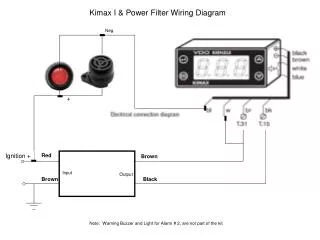
Note: This graphic does not include the capacitor/condenser in the primary ciruit.
Some Spark Plug Design Factors • Size • 14 mm or 18 mm • Reach • Where the spark is placed in the cylinder • Heat range • How fast or slow the plug will dissipate heat • Electrode material • Copper and platinum most common
Types of Engine Position Sensors • Magnetic pulse generator • Consists of a reluctor and pickup coil. • Metal detection sensor • The electromagnet is in the pickup coil. • Hall-effect sensor • Produces a square wave signal. • Is most commonly used. • Photoelectric sensor • Uses an LED and moving slotted disc.
Distributor (DI) System Designs • External ignition module • Used on early Ford systems • Module mounted on the distributor • Ford’s TFI system • Module mounted inside the distributor • Most common design • Computer-controlled system
Advantages of EI Systems • No moving parts • Cylinders individually controlled • Longer parts life • Flexible mounting locations • Less radio frequency interference • No timing adjustments • More time for coil saturation
An EI System with a Double-Ended Coil One plug fires during the compression/power stroke and the other fires during the exhaust stroke.
Summary • The ignition system supplies high voltage to ignite the air/fuel mixture. • The arrival of the spark is timed to coincide with the compression stroke of the piston. • The ignition system has two interconnected electrical circuits: a primary circuit and a secondary circuit.
Summary (Cont’d) • The distributor may house the primary switching device plus centrifugal or vacuum timing advance mechanisms. • The secondary circuit carries high voltage surges to the spark plugs. • Ignition timing is directly related to the position of the crankshaft.
Summary (Cont’d) • Computer-controlled ignition eliminates the need for centrifugal and vacuum timing mechanisms. • Nearly all of today’s engines are equipped with an EI system, which does not use a distributor. • There are primarily two different designs of EI systems, coil-on-plug and waste spark.