Download
1 / 31
310 likes | 473 Views
Test Switches & Plugs. Type FT. Type RT. Type PK-2. Agenda. What are Test Switches & Test Plugs? 10 Pole FT Test Switches Features & Uses Design Details Selection & Ordering Information Typical Connection Diagram 10 Pole FT Test Plugs “In-Service Series” Application

E N D
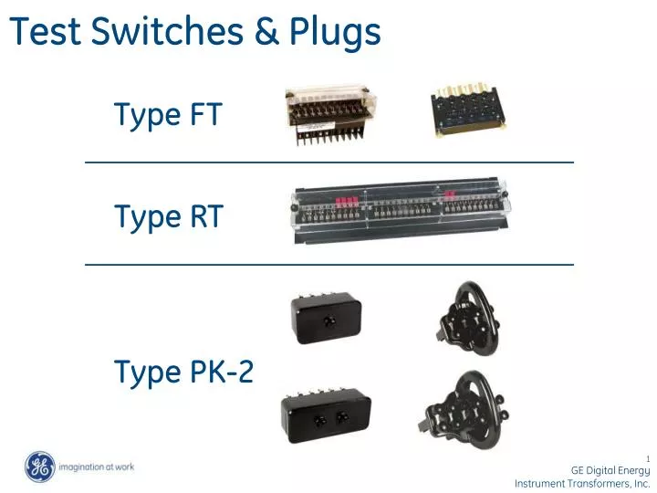
Test Switches & Plugs Type FT Type RT Type PK-2
Agenda • What are Test Switches & Test Plugs? • 10 Pole FT Test Switches Features & Uses Design Details Selection & Ordering Information Typical Connection Diagram • 10 Pole FT Test Plugs “In-Service Series” Application “Separate Source” Application • Typical FT Test Switch Installations • RT Rack Mounted Test Switches • ABB to ITI Cross Reference for FT Test Switches • 4 & 6 Pole PK-2 Test Blocks and Plugs Ordering Information Features & Uses Design Details
What are Test Switches & Test Plugs? Test Switches are devices designed for mounting on switchboard panels for use in conjunction with proper test equipment to facilitate the testing of instruments, meters, and relays. Test Plugs are multi circuit devices designed to be used with test switches to enable easy measurement, calibration, verification or maintenance of instruments, meters, and relays.
FT Test Switches Consist of (2) components 10 Pole FT Test Switch 10 Pole FT Test Plug
10 Pole FT Test Switch -- Features & Uses Semi-flush mounted in front panel Rear termination provisions Configurable to meet customer requirements Black or clear (optional) safety cover Provisions for meter type seal Isolate relay inputs & outputs for injection of current & voltage from separate sources (Use “Separate Source” Test Plug) Measure system currents & voltages during field testing & commissioning (Use “In-Service Series” Test Plug) FTC-066 Test Switch with clear cover FT-066 Test Switch with black cover
10 Pole FT Test Switch ITI P/N FT-099 Front view with cover removed Blades open 10 Poles labeled “A” thru “J”
FT Test Switch – Rear terminals Threaded rear terminals Terminal numbers molded into base Nickel plated brass pan head screws, flats, & locks supplied loose Threaded studs and hex nuts available as option
FT Pole Assemblies “P” = Potential “C-C” Current Shorting (2-Poles Required) “C” = Current Non-Shorting “C-C-C” Current Shorting (3-Poles Required) “C-C-C-C” Current Shorting (4-Poles Required)
10 Pole FT Test Switch Typical Selection table (Note poles A through J……Reference slide 4) Schematic Symbols “P” = Potential (Poles A, B, & J) “C” = Current Non-Shorting (Pole C) “C-C” = Current Shorting (2-Poles Required) (Poles D-E, F-G, & H-I)
FT Test Switch Potential Pole “P” Non-Shorting Blade used for voltage and trip circuits Rear Termination Provision Blade assembly of (1) position potential pole (P)
FT Current Shorting Pole ‘C-C’ Non-Shorting Blade with Current Test Jack Shorting Blade Bottom cam of the shorting blade makes contact with the shorting spring of the pole to the right before disengaging from the jaw (Make before break contact) Jaw Rear Termination Provision Shorting Spring from Non-Shorting Pole to Right Blade assembly of (2) position current shorting pole with current test jack (C-C) Let’s take a look at the current test jack pole to the right
FT Non-Shorting Current Pole ‘C’ Non-Shorting Blade (Open) Current Test Jack for insertion of current test probe Jaw Rear Termination Provision Blade assembly of non-shorting current pole with current test jack (C) --- Part of 2-pole (C-C)
FT Test Switch Handles Molded slot for circuit identification card Optional interlocking bar kit (3) Potential blades tied together with interlocking bar kit
FT Test Switch Part Number System See next slide for typical selection chart
Typical FT Test Switch & Test Plug Selection Chart (2) Pole Current Shorting with Test Jack Position “F-G” Potential Pole Position “A” In-Service Series Test Plug Part Number Test Switch Part Number FT-066
Non-Standard FT Test Switch Specification Form Step 1 The switch body can support 1 to 10 poles in slots marked A through J. Enter a letter from the legend. Leave unused slots blank. B C D E F G H I J A B C D E F G H I J A Example: C C- -C R- -R- -R- -R P P P Legend: P = Potential, Black; T = Potential, Red; O = Potential, Orange; Y = Potential, Yellow; G = Potential, Green; B = Potential, Blue; W = Potential, White C = Current, Non-shorting, Black R = Current, Non-shorting, Red C--C, C--C--C, C--C--C--C = Current, Shorting with current test jack right most position, Black R--R, R--R--R, R--R--R--R = Current, Shorting with current test jack right most position, Red CO = Current, Orange; CY = Current, Yellow;CG = Current, Green; CB = Current, Blue; CW = Current, White Note: Some functions will require more than one slot in the switch body Step 2 If a tie bar is required check this box and draw a dark heavy line over the poles to be joined. In the example above positions H, I, & J will operate together. Step 3 Select a cover style Clear (Installs over open or closed switches) Black (Installs over closed switches only) Step 4 Select a rear terminal type Screws (Standard) Studs (Optional)
10 Pole FT Test Switch Typical Connection FT-076
10-Pole “In-Service Series” Test Plug Used in conjunction with 10-pole test switch Various designs to match specific 10 pole test switches Used to connect devices to measure currents & voltages being applied to the switchboard relays & meters without interrupting or short circuiting the circuit
“In-Service Series” Test Plug Application FT Test Switch Circuit detail of FT test switch prior to insertion of “In-Service Series” Test Plug Existing Meter or Relay Bi-Conductor Paddle & Leads FT Test Switch Circuit detail of FT test switch after insertion of “In-Service Series” Test Plug & connection of external instruments External Current Measuring Instruments Existing Meter or Relay Instrument Ground… Use “Potential Stab”
10-Pole “Separate Source” Test Plug Currently Not Available from ITI Used in conjunction with 10-pole test switch Used to isolate and connect the “out of service” relays or switchboard devices to external test instruments States Part Number FTP10-10 ABB Part Number 1164046
“Separate Source” Test Plug Application FT Test Switch Circuit detail of FT test switch prior to insertion of “Separate Source” Test Plug Existing Meter or Relay Bi-Conductor Paddle & Lead to External Current Supply FT Test Switch Circuit detail of FT test switch after insertion of “Separate Source” Test Plug & connection of external current supply Separate Source Current Supply Existing Meter or Relay
FT Switches – Typical Installations MV Switchgear Relay / Control Panels MV MCC
Multilin Standard RT Model Black panel – 19 inches wide x 5.22” high Up to (3) type FT Switches per panel Meter seal provisions Full width clear cover – handles either open or closed Access to panel mounting hardware prevented with cover installed Padlock provisions Part number system Clear safety shield at rear screw terminal area RT LLLCCCRRR Right FT suffix Center FT suffix Left FT suffix
Optional RT Models Available Full width clear cover – handles either open or closed Up to (3) type FT switches per panel Panel heights: 3.47” 5.22” 5.22” offset 6.97” Panel colors: ANSI 61 & 49 gray Brushed aluminum
FT Test Switch - ABB to ITI Cross Reference (*) Consult factory for other part numbers (*) This cross reference is intended to be accurate; however, all equivalent part numbers are based on available competitor product data only. Therefore this cross reference should be used as a guide only. All recommended ITI configurations to be confirmed by customer before placing orders.
PK-2 Test Blocks & Plugs 4 & 6 Pole PK-2 Test Plug 4 & 6 Pole PK-2 Test Block P/N 6422120G1 4-Pole; surface mount on 1 to 2 inch panels P/N 6422120G2 6-Pole; surface mount on 1 to 2 inch panels P/N 6422120G3 4-Pole; semi-flush on 0.12 inch panels surface mount on 0.12 to 0.5 inch panels P/N 6422120G4 6-Pole; semi-flush on 0.12 inch panels surface mount on 0.12 to 0.5 inch panels P/N 6129533G1 4-Pole P/N 6129533G2 6-Pole
PK-2 Test Blocks – Features & Uses Semi-flush or surface mounted Cover removal automatically shorts current circuits Rear termination provisions Provided with unmounted auxiliary contacts, jumpers, and hardware for field installation into test block Reference application data for typical arrangements of contacts & jumpers http://www.multilin.com; Type PK-2 in “search”; Select “PK-2 test Blocks and Plugs – Product Information”; Select “Brochures” Routine testing accomplished by removing cover and inserting the properly connected test plug Normal connections restored by replacing cover
PK-2 Test Blocks 3 1 4 6-Pole Test Block with Cover Removed (Component parts defined below) 2 Legend: • Auxiliary Contact Maintains circuit with cover or plug not installed • Auxiliary Contact Short circuits CT with cover or plug not installed • Jumper Used with contacts (2) or (4) -- short circuits CT or interconnects phases when cover-fastening stud is to be bypassed • (4) Auxiliary Contact Equal to one pole of contact (2) & used with jumper (3)
PK-2 Test Plugs Test Links supplied with plug (4) with the 4-pole (6) With the 6-pole Links can be installed vertically or horizontally Refer to application data for typical test link arrangements http://www.multilin.com; Type PK-2 in “search”; Select “PK-2 test Blocks and Plugs – Product Information”; Select “Brochures” Test Links