Download
1 / 11
110 likes | 201 Views
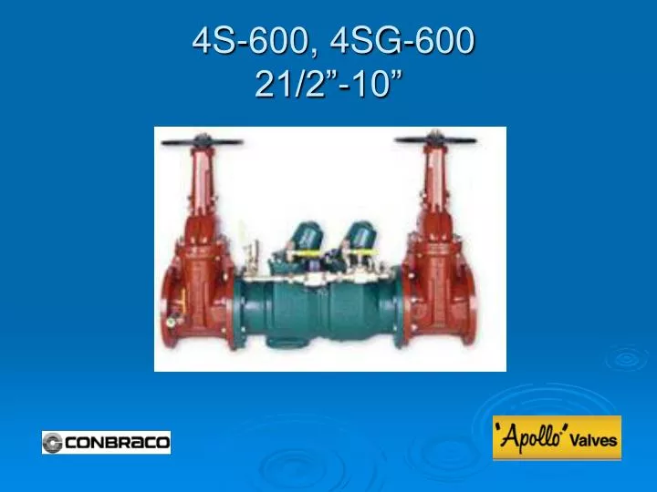
4S-600, 4SG-600 21/2”-10”. Modification Overview. Production of the 4S-600 aka (DCDA4S) began in 1999. The 4S-600 utilizes a ½” 4S-103 bypass. The 4SG-600 was introduced in 2008. The “G” indicates grooved end body. Check Cover Removal. Cover is sealed by a gasket.

E N D
Modification Overview • Production of the 4S-600 aka (DCDA4S) began in 1999. • The 4S-600 utilizes a ½” 4S-103 bypass. • The 4SG-600 was introduced in 2008. The “G” indicates grooved end body.
Check Cover Removal • Cover is sealed by a gasket. • Cover has no spring load. • For the 21/2”-6” size, unscrew black plastic spring cap. • Remove bolts, cover and gasket. • 8-10” – cover has spring load approximately ¼”.
Check Valve Removal • Check valve module. • Module is o-ring sealed. • 8”-10”- spring module is separate from the check module. • Gently pry the module from the body.
Disassemble Check Valve 2½” - 6” • The module is spring loaded. ** Do not remove the socket head bolt. • Unscrew and remove the spring assembly from the module by placing a wrench on the flats provided. • Do not disassemble spring assembly any further.
Check Disc Replacement 2½” – 6” • Once the spring assembly is removed, spring load is released. • Remove the retaining screws and disc retainer. • Remove the seat disc.
Disassemble Check Valve 8”-10” • The check module is made of brass. • The spring module is self contained and is free once the cover has been removed. • Do not disassemble spring assembly any further.
Check Disc Replacement 8”–10” • Remove the retaining screws and disc retainer. • Remove seat disc.
Check Seat Removal • The check seat is part of the check module and can not be removed. • If the seat is damaged, the complete check module will need to be replaced.
Check Valve Reassembly Notes 2½”-6” • Reassemble checks in reverse order. • Lubricate o-rings. • A pry bar may be needed to aid in seating the check assembly into the body. • Spring cap needs only to be snug.
Check Valve Reassembly Notes 8”-10” • 8”-10”- Insure that the cam positioner is flipped down on the swing arm of the check module. • 8”-10”- When replacing the spring assembly, make sure to place cam end of spring on both cam rollers of the check module.