Download
1 / 40
430 likes | 709 Views
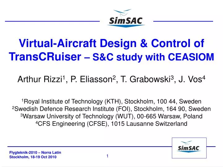
Virtual-Aircraft Design & Control of TransCRuiser – S&C study with CEASIOM Arthur Rizzi 1 , P. Eliasson 2 , T. Grabowski 3 , J. Vos 4 1 Royal Institute of Technology (KTH), Stockholm, 100 44, Sweden 2 Swedish Defence Research Institute (FOI), Stockholm, 164 90, Sweden

E N D
Virtual-Aircraft Design & Control of TransCRuiser– S&C study with CEASIOM Arthur Rizzi1, P. Eliasson2, T. Grabowski3, J. Vos4 1Royal Institute of Technology (KTH), Stockholm, 100 44, Sweden 2Swedish Defence Research Institute (FOI), Stockholm, 164 90, Sweden 3Warsaw University of Technology (WUT), 00-665 Warsaw, Poland 4CFS Engineering (CFSE), 1015 Lausanne Switzerland
CEASIOM Design Tool – outcome of SimSAC Analyze/improve flight dynamics Specification & Design to Canard Configuration Creation Tabular Aero Data Comparison with WT data Prediction Flying Qualities - Low & transonic speeds Static stability – static margin: tradeoffs Dynamic stability – linear & nonlinear (flight simulator) Augmented Stability Demo Flight simulation Contents
SimSAC EU-Project Partnership SimSAC:Simulating Aircraft Stability and Control Characteristics for Use in Conceptual Design EU FP 6 STREP project Project coordinator: Prof. A. Rizzi, KTH
SimSAC Goal: Design Flight Control System Earlier • Compute Aerodyn Dataset • variable-fidelity CFD • predict flight dynamics • Use in conceptual design Aerodynamic Tools for S&C
CEASIOM Design Tool Flight Dynamics
Original TCR: poor trim ability large , Different configurations investigated Wing further fore (design parameter) Three lifting surfaces All-moving canard (vary location & size) Design of wind tunnel model One moving surface for longitudinal control No engines Configuration Re-Design
DesignChoice – Staticstabilitymargin Trimcondition M Static stable ac CG Dilemma ! Staticmargin L KngrowswithMa Response heavy at high speed CG = 38.3m
Predict Flying Qualities: solve Flight Dyn Eqs • s – state vector (8) • A – inertia matrix • F – general forces Linearize ( stability derivatives...)
FaeroInterpolation Process - Kriging Aero-data Data from source • Database constructed • DACE Kriging toolbox: • Linear base model, • Input & output scaled (0,1) • Manual choice corr. length Mach α
Weight, Inertia & Balance Total Length 63.87 m Total Wingspan (bref) 44.66 m Total Canard Span 12.00 m Total Height 11.70 m Fuselage Diameter 3.70 m MAC 16.06/11.77 m, Wing reference area Sref = 489 m2, Reference point, moment x = 35.00 m, z = 0 m Center of gravity x = 38.33 m, z = 0 m W&B/ACBuilder: J.Munoz, S Ricci, ...
Aero Data & Handling Qualities – Longitudinal Dynamics Cm(a) for zero canard deflection WT data Comparison Control authority: Canard stall
Trim & Flying Qualities – low speed Trim Sensitivity small Phugoid a M.50 M.35 dCanard 120-180 m/s, 1km – 3km M 0.35 – 0.50 Short period
Trim & Flying Qualities – transonic speed a Phugoid Short period dCanard Transonic dip M.65 M=1
Flow Physics transonic dip 220ms 250 270 286
Linear & NonLinear Stability – Stick fixed Eigenvalues 276 m/s 10km, a = 0.5 All modes stable (barely ...) Flight simulation da = -0.3o: Slooowly damped da = -3.0o: See-saw pitchup ... Cobra manuver Wind gust - disturb α small large Time Histories a: AoA q: attitude
Augmented Stability SAS OFF SAS ON
Flying Qualities with Augmentation – low speed Phugoid Short Period ON OFF ON OFF ON Dutch Roll OFF
CEASIOM proven useful ! Trim & static margin chosen correctly Good canard sizing & placement Verified by WT no major pitfalls Stability Augmentation good flying qualities Low-speed stick-fixed qualities improved Transonic disturbance damped Canard authority sufficient Allows concept designer to work with control tools to sort out: What can be fixed by control system What changes in configuration is needed CEASIOM lives on ! Community of users Open software Visit www.ceasiom.com Join us ! Conclusions
Thanks For Your Attention !
CEASIOM Predicts T-tail Flutter Clamped node Stick Model: beam elements & lump masses Hor. Tail roll mode 3 4.3 Hz Fin bending mode 1 1.6 Hz V-g diagrams, sea-level
Aircraft Motion: Non-Linear Dynamical System • s – state vector (8) • A – inertia matrix • F – general forces linearize
Raymer volume coefficient ~ 0.1 lC = 28 m SC = 60 m2 MAC = 11.77 m S = 489 m2 cC ≈ 0.29 What if done by Handbook Method Handbook methods not applicable to unconventional configs. such as the TCR
TCR Design: Specification Payload ‘Loose ideas’ to be Worked out: MTOW~ 180 t , R~ 10000 km , No Pax~ 200 Mc = 0.97
Fused Aerodynamic Dataset Mach
Fused Aerodynamic Dataset Mach
Evolution of pitching moment & lift coefficients with Mach/speed Also breakpoints – no second-opinion – do we believe CFD ?? TCR - CFDsim - Machdependence
Baseline Design • InitialsizingwithSaab in-housemethod. • Baselinedesign: input for CEASIOM.
TCR T-tail flutter Clamped node Stick Model: beam elements & lump masses Hor. Tail roll mode 3 4.3 Hz Fin bending mode 1 1.6 Hz • V-g diagrams, M∞=0.50, • sea-level
Trim & longitudinal static stability Results from SDSA, for h=10 km and V = 240 m/s (M=0.8) TCR-C2 TCR-C17
Trim & longitudinal static stability Results from SDSA, for h=10 km and V = 240 m/s (M=0.8) TCR-C17 TCR-C8
Trim & longitudinal static stability Results from SDSA, for h=10 km and V = 240 m/s (M=0.8) distance W-C dC , static margin SC
Construct Windtunnel Model • Exterior shape • - Export IGES • PoliMi designed • interior structure