Download
1 / 17
170 likes | 332 Views
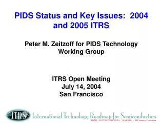
PIDS Status and Key Issues: 2004 and 2005 ITRS Peter M. Zeitzoff for PIDS Technology Working Group ITRS Open Meeting April 13, 2005 Munich, Germany. PIDS = P rocess I ntegration, D evices, and S tructures Main concerns MOSFET, memory, and passive devices and structures

E N D
PIDS Status and Key Issues: 2004 and 2005 ITRSPeter M. Zeitzoff for PIDS Technology Working GroupITRS Open MeetingApril 13, 2005Munich, Germany
PIDS = Process Integration, Devices, and Structures Main concerns MOSFET, memory, and passive devices and structures Device physical and electrical characteristics and requirements Broad issues of device and circuit performance, density, and power dissipation, particularly as they drive overall technology requirements Reliability PIDS Scope
Logic High-performance Low-power, focused on mobile applications Memory DRAM Non-volatile memory (NVM) Reliability PIDS Subcategories
2004: scaling unchanged from 2003 DRAM half-pitch: 3 year cycle 90nm in 2004, 65 nm in 2007 2005 and beyond: survey results DRAM half pitch (F): same as in 2003 ITRS a=(cell area)/F2: a=8 through 2007, a=6 thereafter Area size factor (% of chip area taken up by storage cells): 63% through 2007, 56% thereafter STC storage node dielectric: the same as 2003 ITRS DRAM
NOR Flash Reaching scaling limit rapidly, at 45nm or 32nm node for floating gate device. MLC becomes mainstream – double density. Nanocrystal device not ready, and has scalability issues. NAND Flash Cell size becomes ~ 4F2 at 65nm node. MLC becomes mainstream – double density. More scalable than NOR – thus may become technology driver. At 4F2 – drives isolation, poly, metal-1 and contact design rules. However, floating gate coupling a serious challenge – potential show stopper. Used almost all new tricks to get to 4F2 at 65nm – cell size may get larger after 65nm. Non-Volatile Memory (NVM): Flash
Ferro-Electric RAM (FeRAM) FeRAM minimum dimension scaling lags flash scaling by six or more years Fast and low power program/read – ideal for RFID, smart card. Key issues are ferroelectric material and capacitor size – 3D needed Silicon Oxide Nitride Oxide Silicon (SONOS) New in 2003 PIDS (transferred from 2001 ERD): in mainstream production 3Q’04 2-bit/cell due to localized charge storage Scalability expected similar to floating gate device. No floating gate coupling issues NVM (con’t.)
Magnetic RAM (MRAM) New in 2003 PIDS (transferred from 2001 ERD): limited production in 1Q’05 Big breakthrough in 2003 in switching uniformity Generating and confining magnetic field are still key challenges Phase Change RAM (PCRAM) New in 2005 PIDS (transferred from 2003 ERD): mainstream production expected soon For near term years, minimum dimension lags Flash by 3 years Key challenges are switching current and material interface properties NVM (con’t.)
High-k Gate Dielectrics Dielectric breakdown; Transistor instability Metal Gate Ion drift, VTH stability, oxidation; thermal-mechanical Cu/ Low k Electromigration and voiding; stability of interfaces; TDDB Impact of porous, weaker, less thermally conductive dielectrics Packaging Solder bumps; fracture; EM in packaging; CTE mismatch Design & Test for Reliability Reliability simulation; Reliability screens Reliability: 2004 Top 5 Near-Term Challenges
Reliability risk is growing New materials (e.g., high k/metal gate; low k) and new devices (e.g., FINFET) and new packaging Introduce new and/or modified failure mechanisms Mechanisms need to be identified, modeled and controlled Have less-than-historic time and resources to ensure reliability Difficult tradeoffs may require reduced reliability margins or entail higher risk Need new Design for Reliability tools and reliability screens Need to sustain current high reliability levels in spite of unprecedented changes Reliability: Key 2005 Issues
Near Term Challenges Combine High-k & Metal Gate into one near-term challenge since they are likely to be introduced simultaneously Add NBTI (Negative Bias Temperature Instability) P channel degradation; Issue for scaling and burn-in Add Long Term Challenge Reliability of novel post-CMOS devices and materials Need to identify, model, accelerate and control failure modes Reliability: Prospective 2005 Changes to Top Challenges
Simple models capture essential MOSFET physics embedded in a spreadsheet Verified vs. MASTAR (detailed analytical device model from STM) and literature data Initial choice of scaled MOSFET parameters is made Using spreadsheet, MOSFET parameters are iteratively varied to meet ITRS targets Types of Logic High Performance (HP): target is historical 17%/year transistor performance increase Low Power (especially for mobile applications): target is specific, low level of leakage current Low Standby Power (LSTP): very low power (i.e., cellphone) Low Operating Power (LOP): low power, rel. high performance (i.e., notebook computer, video camcorder 2004 scaling results unchanged from 2003 ITRS Logic: 2004 Scaling Approach and Categories
2004: Low Power & High Performance (HP) Intrinsic Transistor Delay, t (lower delay = higher speed) Leakage Current (HP: standby power dissipation issues) 10.0 1.E+00 HP (A/m) 1.E-01 LSTP 1.E-02 t (ps) LOP 1.0 LOP 1.E-03 LSTP Requirement HP Requirement: 17%/yr, historical rate 1.E-04 0.1 1.E-05 2005 2009 2013 2017 2005 2009 2013 2017 Calendar Year Calendar Year
First Year of “Volume Production” 2020 2015 2010 2005 2000 HP Strained Si High k Gate Dielectric LP HP HP Metal Gate HP Fully Depleted SOI HP Multi Gate MOSFET Others = Low Power Applications = High Performance Applications LP HP Driver: The “CMOS Change Crunch” Multiple, Big Changes Over Next 7 Years
1.E+02 EOT 20 1.E+01 15 1.E+00 EOT (A) Jg (A/cm2) Jg,sim,SiON 1.E-01 10 1.E-02 Jg,max 5 1.E-03 0 1.E-04 2003 2005 2007 2009 2011 2013 2015 2017 Calendar Year LSTP: EOT and Gate Leakage Current Density (Jg) Scaling 1.E+03 25
Complete re-evaluation of the scaling scenario Utilize MASTAR (detailed analytical device model from STMicroelectronics) High-performance logic: continue to target 17%/year average performance increase Low-power logic: continue to target low leakage current Particularly LOP: definition, tradeoff between and fit of LOP between LSTP and high-performance logic Parallel paths (reflect reality) Review timing and sequence of key technology innovations 2005: Potential Changes and Issues (Preliminary)
2003 ITRS----- 2005 ITRS (Prospective) 2005: Potential Parallel Paths
Memory Rapid scaling continuing Numerous different types of NVM, with unique attributes and scaling scenarios Reliability Ensuring reliability for numerous and rapid technological innovations is a critical challenge Nevertheless, need to sustain current high reliability levels Logic High-performance logic: performance increases by 17%/yr. ratehigh leakage current Low-power logic: low leakage currentreduced performance Numerous and rapid technology innovations required 2005 ITRS: re-evaluation of scaling scenarios, timing and sequence of technology innovations Summary