Download

1 / 21
210 likes | 342 Views
Radiation Hard Sensors for the Beam Calorimeter of the ILC. C. Grah 1 , R. Heller 1 , H. Henschel 1 , W. Lange 1 , W. Lohmann 1 , M. Ohlerich 1,3 , R. Schmidt 1,3 , S. Schuvalow 1 , K. Afanaciev 2 , A. Ignatenko 2 , J. Gajewski 4 , S. Kulis 4 , A. Rosca 5 , Z. Krumshteyn 6 , A. Sapronov 6

E N D
Radiation Hard Sensors for the Beam Calorimeter of the ILC C. Grah1, R. Heller1, H. Henschel1, W. Lange1, W. Lohmann1, M. Ohlerich1,3, R. Schmidt1,3, S. Schuvalow1, K. Afanaciev2, A. Ignatenko2, J. Gajewski4, S. Kulis4, A. Rosca5, Z. Krumshteyn6, A. Sapronov6 N48-4, Thursday, Nov. 1st 1 DESY, Zeuthen, Germany 4 AGH University of Cracow, Poland 2 NCPHEP BSU, Minsk, Belarus 5 West University of Timisoar, Romania 3 BTU Cottbus, Germany 6 JINR, Dubna, Russia
Contents • Very forward region of the detectors for the International Linear Collider and the beam calorimeter - BeamCal • Materials under investigation • Measurement of Charge Collection Distance (CCD) and high dose test beam • Radiation hardness of • polycrystalline Chemical Vapor Deposited (CVD) diamonds • GaAs • singlecrystalline CVD diamonds • Conclusions C.Grah: Radiation Hard Sensors for BeamCal
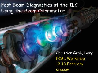
Very Forward Region of the ILC Detectors BeamCal Interaction point • EM calorimeter with sandwich structure: • 30 layers of 1 X0 • 3.5mm W and 0.3mm sensor • Angular coverage from 5mrad to 28 mrad • Purpose: • hermetic detector, important for particle searches • optimize luminosity LDC • e+e- pairs from beamstrahlung are deflected into the BeamCal • Several MGy per year strongly dependent on the beam and magnetic field configuration • => Radiation hard sensors, qualified for up to 10 MGy/a C.Grah: Radiation Hard Sensors for BeamCal
Materials under Investigation (courtesy of IAF) • Samples from two manufacturers: • Element SixTM • Fraunhofer Institute for Applied Solid-State Physics – IAF • 1 x 1 cm2 • 200-900 μm thick (typical thickness 300μm) • Ti(/Pt)/Au metallization • pCVD diamonds: • radiation hardness under investigation (e.g. LHC pixel detectors) • advantageous properties like: high mobility, low εR = 5.7, thermal conductivity • availability on wafer scale • GaAs: • semi-insulating GaAs, doped with Sn and compensated by Cr • produced by the Siberian Institute of Technology • available on (small) wafer scale • sCVD diamonds: • available in sizes of mm2 • 500 µm thick detector, 87 5x5 mm pads • Mounted on a 0.5 mm PCB with fanout • Metallization is V (30 nm) + Au (1 µm) • Works as a solid state ionization chamber • structure is provided by metallization • scCVD diamond • area 5x5 mm2, thickness 340 µm, • metallization Ø3mm C.Grah: Radiation Hard Sensors for BeamCal
MiP Response of pCVD Diamond PA Sr90 ADC diamond delay Sr90 source Scint. discr PM1 & Gate discr PM2 Preamplifier Sensor box Trigger box typical spectrum of an E6 sensor C.Grah: Radiation Hard Sensors for BeamCal
CCD Measurement ~ CCD CCD = Charge Collection Distance = mean drift distance of the charge carriers = charge collection efficiency x thickness (assuming 36 ionized e-h pairs per μm) Counts ADC Channels ~ charge C.Grah: Radiation Hard Sensors for BeamCal
High Dose Irradiation Superconducting DArmstadt LINear ACcelerator Technical University of Darmstadt • Irradiation up to several MGy:10 ± 0.015 MeV and beam currents from 10 to 50 nA corresponding to 60 to 300 kGy/h. • Keeping the sensor under bias permanently. • This is a much higher dose rate compared to the application at the ILC (~1 kGy/h)(1 MGy = 100 Mrad is deposited by about 4 x 10¹⁵ e-/cm2) preamp box Beam setup absorber collimator C.Grah: Radiation Hard Sensors for BeamCal
Test Beam Setup Beam current is measured using the Faraday cup. Together with correction factors from a GEANT4 simulation we determine the absorbed dose with an error of less than 10%. Beam Collimator Sensor Faraday cup C.Grah: Radiation Hard Sensors for BeamCal
Irradiation of Polycrystalline CVD Diamond decrease pumping depumping by UV After absorbing 5-6 MGy: CVD diamonds still operational. • Very low leakage currents (~pA) after the irradiation. • Decrease of the charge collection distance. • Generation of trapping centers due to irradiation. C.Grah: Radiation Hard Sensors for BeamCal
Comparison to Data from 2006 (Percentage of the maximum CCD) Results from 2006 have been confirmed using lower beam currents. Very similar behavior of all samples for high doses. Keep in mind that the sensors are continuously in their pumped state during the irradiation. C.Grah: Radiation Hard Sensors for BeamCal
Irradiation of GaAs Irradiated one individual pad of each prototype to about 1 – 1.5 MGy. ~ 80% decrease Starting at about 50% of the sensor thickness. Ending at about 3 % CCD vs Dose CCD vs HV before and after (500µm thickness) C.Grah: Radiation Hard Sensors for BeamCal
GaAs after Irradiation Leakage currents increase by about a factor of 2...but this time it is in the μA range. Partially irradiated pads show two very distinct signal peaks. High: signal from not irradiated area Low: signal after ~1.5 MGy C.Grah: Radiation Hard Sensors for BeamCal
Irradiation of Singlecrystalline CVD Diamond before irradiation after irradiation Starts at 100% Reduction of measured signal, but still operating after 5 MGy. (~340µm thickness) C.Grah: Radiation Hard Sensors for BeamCal
Summary • BeamCal is an important part of the instrumentation of the very forward region of the ILC detectors. • The requirements on the radiation hardness of the BeamCal sensors are challenging. Up to 10MGy of TID will be accumulated close to the beam. • Diamonds, GaAs and also Si (not covered here) are materials under investigation for this task. • High dose irradiation using 10MeV electrons shows: • all CVD diamonds stay functional even after absorbing up to 5 MGy and more. • GaAs was irradiated to 1-1.5 MGy. The CCD (efficiency) decreases and the leakage currents increases to critical levels (without cooling). • poly- and singlecrystalline CVD material show a loss of charge collection, but stay functional with very low leakage currents. Thanks to: EUDET, the S-Dalinac crew, Norhdia, Worldlab and Intas http://www-zeuthen.desy.de/ILC/fcal/ C.Grah: Radiation Hard Sensors for BeamCal
Backup Slides C.Grah: Radiation Hard Sensors for BeamCal
Very Forward Region of the ILC Detectors • The purpose of the instrumentation of the very forward region is: • Electron veto down to lowest angles • supplying a fast luminosity signal to the feedback system of the accelerator. ~20 cm Interaction point ~ 25 cm LDC BeamCal • EM calorimeter with sandwich structure: • 30 layers of 1 X0 • 3.5mm W and 0.3mm sensor • Angular coverage from 5mrad to 28 mrad • Moliére radius RM ≈ 1cm • Segmentation between 0.5 and 0.8 x RM C.Grah: Radiation Hard Sensors for BeamCal
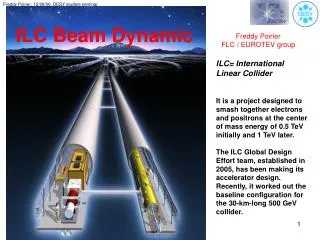
The Challenges for BeamCal e+ e- e+ e- γ Interaction γ e- e- e.g. Breit-Wheeler process Creation of beamstrahlung at the ILC ≈ 5 MGy/a • e+e- pairs from beamstrahlung are deflected into the BeamCal • 15000 e+e- per BX • => 10 – 20 TeV total energy dep. • Several MGy per year strongly dependent on the beam and magnetic field configuration • => radiation hard sensors needed qualified for 10 MGy/a V.Drugakov 6X0 Energy deposition and spectrum of shower particles. C.Grah: Radiation Hard Sensors for BeamCal
Procedure Apply HV to the DUT Measure CCD ~20 min Irradiate the sample ~1 hour Correction factors are obtained from a GEANT4 simulation of the geometry • R = NFC/NSensor ~ 0.96 • <Edep>/particle = 5.63 MeV/cm During the irradiation the Faraday cup current is monitored and used to calculate the accumulated dose with a total error ofΔD/D < 10% C.Grah: Radiation Hard Sensors for BeamCal
CCD Behaviour after Irradiation Before irradiation After irradiation before UV illumination After irradiation, UV illuminated Value used at testbeam C.Grah: Radiation Hard Sensors for BeamCal
Comparison to Earlier Study before/after ~ 7MGy (irradiated in 2006) strong „pumping“ after irradiation ▪before irradiation ▪after irradiation After removal of the surface (2.5μm) and remetallization => no change C.Grah: Radiation Hard Sensors for BeamCal
Polarization of Single-crystalline CVD Diamond Observation a) Observation b) • Signal current and • from MIPs decreases. • No trapping-detrapping on short timescales MIP response is dependent on time (after setting HV) and rate Dose calculation uncorrected! Prediction at 200V (switching HV) Measurement at 200V (switching HV) Prediction at 200V Homogeneous creation of traps + creation of eh pairs by a MIP plus electric field leads to polarization. Prediction at 100V Measurement at 100V Dose calculation uncorrected! C.Grah: Radiation Hard Sensors for BeamCal