Download
1 / 75
770 likes | 816 Views
United Arab Emirates University Collage of Engineering Graduation Project Unit Graduation Project II. Enzymatic Hydrolysis of Cellulosic Waste Biomass for bio-ethanol production. Done by: Mohamed Husain Al Hosani 200602594 Yasser Salem Zooba 200501245

E N D
United Arab Emirates University Collage of Engineering Graduation Project Unit Graduation Project II Enzymatic Hydrolysis of Cellulosic Waste Biomass for bio-ethanol production Done by: Mohamed Husain Al Hosani 200602594 Yasser Salem Zooba 200501245 Abdulla Salem Al- Hammadi 200514949 Salem Saeed Al- Kaabi 200415906 Advisor: Dr. Sulaiman AlZuhair
Outline • Objective • Introduction and Literature Background • GP1 Summary • Detailed Design • Pretreatment • Enzymatic Hydrolysis • Fermentation • Distillation Column • Heat Exchanger • Detailed Economical Study • HAZOP Study • Project Management • Conclusion
Objective Design a plant to produce 1 ton/hr of ethanol from cellulosic waste. Enzymatic hydrolysis is used for cellulose break-up into glucose.
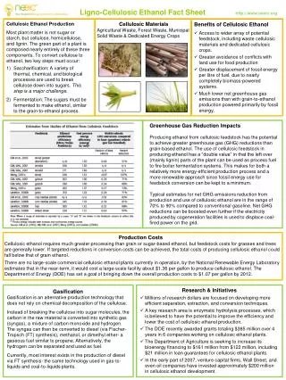
Introduction • Energy: • Energy plays a vital role in socio–economic development and raising standards of human beings. • Fossil fuels is the most common energy source in use today. • New sustainable sources of energy are being developed such as biofuels, solar, wind, geothermal, nuclear, and other forms of renewable energy.
Introduction • Biofuels • Biofuels are sources of energy derived from biomasses. • Plants store solar energy into chemical energy inside their carbohydrate bonds through the photosynthesis. • Bio-ethanol is considered one of the main actors in the bio-fuel market.
Introduction • First generation feedstock (starch) • Bio ethanol produced from food source (e.g. corn) raised an ethical problem. • Second generation feedstock (cellulose) • Not readily fermentable. • Lignocellulosic materials need to be converted to simple sugars before fermentation.
Bio-ethanol in UAE UAE heavily depends on the fossil fuels. There are more than 40 million palm trees in UAE. Each palm tree produces about 15 kg of waste fronds per year. Palm fronds contain 58% of cellulose and 22% of hemicellulose. These are high percentage compared with other biomasses like corn stover.
GP1 Summary • Main Process Steps • Pretreatment • Enzymatic Hydrolysis • Fermentation • Purification and storage
Pretreatment • To separate the cellulose from the lignin seal and the hemicellulose to allow subsequent hydrolysis step. • Steam Explosion was chosen
Hydrolysis • To break down long chain cellulose into smaller fermentable simple sugars. • Separate enzymatic hydrolysis and fermentation was used
Fermentation • A process of driving energy from the oxidation of organic compound. • Anaerobic process and fermenting by yeast was chosen.
Mass Balance • Flow Rates, Compositions and Conversions should be specified. • Steady State process is assumed. • ∑ nixi= ∑ noxo + Generation – Consumption • 5,000 kg of raw material 1,000 kg of ethanol
Energy Balance • Flow Rates, Temperatures, Pressures and Energy stored in each stream should be determined. • For steady state system: • ∑Hi,out= ∑Hi,in + W + Q • Enthalpy of each component can be calculated using the following equation: • Tref = 25oC
Energy Integration • Use hot stream (instead of external heating source) to heat another stream. • Increase the capital cost. • Reduce operating cost.
Pretreatment • Steam Explosion: • Batch reactor, where the heating of the milled lignocellulosic substrates at high temperatures and pressures. • Followed by mechanical disruption by sudden reduction of the pressure to atmospheric. • 180–230 °C, <10 bar and 30 min. • High conversion.
Pretreatment • Uncatalysed Steam Explosion : • Batch or continues reactor, Using the water as the reagent. • Rapid decompression causing gas expansion. • 180–230 °C for 30 min in batch system. • Lower conversion
Pretreatment • Selected Data: • 2-L reaction vessel • 4 bar • 100g of raw material per batch. • Xylose is 18% of the raw material.
Pretreatment Plot the time-concentration reaction as first and second order reaction it was found that the R2=0.749, R2=0.681.
Pretreatment k : slope of (1-x) vs. t, which was found to be 0.274. For conversion 0.83, 6.4 minutes per batch needed. Reactor size needed for batches of 5000 kg/hr is 10.7 m3
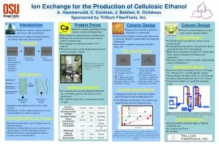
Enzymatic Hydrolysis The conversion of cellulose to glucose is done in bioreactor using enzymes. Usually, enzymes are inhibited by the reaction products. Enzymes that produces glucose are inhibited by glucose (human body). 23
Inhibition Effect For high conversion, inhibition effect increases the size of reactor more than 5 times !!! 24
Membrane Reactor Molecular weight of enzyme: 35,000 to 65,000 g/mol. Molecular weight of cellulose: more than 300,000 g/mol. Molecular weight of glucose: 180 g/mol. 25
Membrane Reactor 2 functions (reaction and separation) in 1 reactor. Inhibition effect will decrease dramatically because of product removal by membrane separation. 26
Fed Batch 27
Hydrolysis Reaction C : Cellulose concentration B : Cellobiose concentration G : Glucose Concentration r : Reaction rate k : rate constant Cellulose (C) Cellobiose (B) Glucose (G)
Hydrolysis Reaction F : Mass flow rate o : Outlet i : Inlet V : Volume v: Volumetric Flow r : Reaction rate X : Conversion
Hydrolysis Reaction Normal iterative solution of MS. excel
Enzyme Losses Concentration of cellulose in the reactor is 1443 g/L, which correspond to 43 tones. Activity of cellulase per gram of cellulose needed = 475 IU. The activity of cellulase is 710 IU/(g cellulase). The total weight of cellulase needed = 27.7 tones, which correspond to a concentration of 923 g/L.
Enzyme Losses Flow rate of water in the reactor outlet is 989 L/hr. Amount of enzyme that will escape from the reactor is 912.8 kg/hr. Since 99% of the outlet liquid will be recycled to the reactor, enzyme loss = 0.01 x 912.8 = 9.12 kg/hr. Similar calculations were done to k2\, losses were found to be 17.55 kg/hr.
Fermentation Bio reactor: • Engineered device or system that supports a biologically active environment. • Involves organisms or biochemically active substances derived from such organisms. • classified as batch, fed batch or continuous.
Fermentation Batch reactor: • Generic term for a type of vessel widely used in the process industries. • Advantages : • A single vessel can carry out a sequence of different operations without the need to break containment. • Useful when processing, toxic or highly potent compounds.
Fermentation • Continuous reactors: • Alternatively referred to as flow reactors carry material as a flowing stream. • Advantages: • Continuously fed into the reactor and emerge as continuous stream of product. • A wide variety of chemical and biological processes. • Example of continuous reactors: • Continuous stirred-tank reactor (CSTR). • Chemical environment is static (chemo stat).
Fermentation • Chemo stat bio reactor: • Continuous reactor. • Volume constant. • Control microorganism.
Fermentation Chemo state bio reactor:
Fermentation • Chemo state bio-reactor design: • Growth Equation:
Fermentation Chemo state bio reactor: substrate equation: Ks is the maximum growth of substrate.
Fermentation Chemo state bio reactor: Main equation: qp is the specific rate of extra cellular product formation. is the yield yeast. is the yield of product .
Fermentation Relation between the conversion and the volume of the reactor 45
The type of heat exchanger was chosen and to be designed is shell and tube counter current heat exchanger because of: High area per volume ratio. Easily cleaned. Low operating pressure. Heat Exchanger Design
Heat Exchanger Design • Step1 : shell and tube physical properties: • Step2: calculate the heat transfer rate (KJ/hr) • Step 3: Find (ΔT)LMTD
Heat Exchanger Design Step 4 : Set F = 0.9 Step 5: assume a value for U = 300 W/m2.C Step 6: calculate heat transfer area (m2) Step7: choose initial values for L, Do and Di L = 4.5 m , Do = 0.02667 m , Di = 0.021 m 48
Heat Exchanger Design Tube Side Calculations : Step 1 : calculate the area of one tube Step2 : calculate the number of tubes (Nt), Nt = 180 tubes Step3 : tube side velocity (m/s), uin = 0.457 m/s 49
Heat Exchanger Design Step 4 : calculate Reynolds number , Re = 13129 turbulent flow Step 5 : calculate Nusselt number (Nu), Nu = 0.023 Re0.8 Pr0.4 = 85.060 Step 6 : heat transfer coefficient 50