Download
1 / 1
10 likes | 112 Views
Analogue optical links experiences in the framework of the SKA/BEST activities. Federico Perini. INAF-IRA (I). Motivation: Necessity to bring the signal from the BEST Front End, on the antenna focal lines, to the central processing room.

E N D
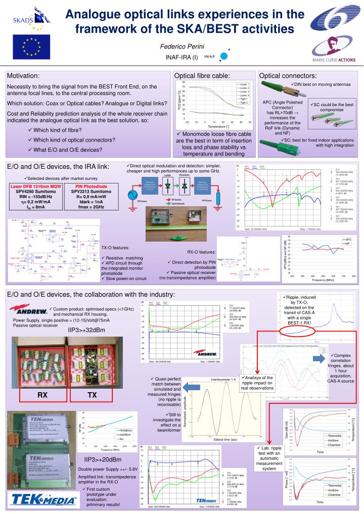
Analogue optical links experiences in the framework of the SKA/BEST activities Federico Perini INAF-IRA (I) • Motivation: • Necessity to bring the signal from the BEST Front End, on the antenna focal lines, to the central processing room. • Which solution: Coax or Optical cables? Analogue or Digital links? • Cost and Reliability prediction analysis of the whole receiver chain indicated the analogue optical link as the best solution, so: • Whichkindof fibre? • Whichkindofopticalconnectors? • What E/O and O/E devices? Optical fibre cable: Optical connectors: • DIN best on moving antennas APC (Angle Polished Connector) has RL>70dB → increases the performance of the RoF link (Dynamic and NF) • SC could be the best compromise • Monomode loose fibre cable are the best in term of insertion loss and phase stability vs temperature and bending • SC: best for fixed indoor applications with high integration E/O and O/E devices, the IRA link: • Direct optical modulation and detection: simpler, cheaper and high performances up to some GHz. • Selected devices after market survey Laser DFB 1310nm MQW SPV4260 Sumitomo RIN = -155dB/Hz = 0,2 mW/mA Ith = 8mA PIN Photodiode SPV3313 Sumitomo = 0,9 mA/mW Idark = 1nA fmax = 2GHz • TX-O features: • Resistive matching • APD circuit through the integrated monitor photodiode • Slow power-on circuit • RX-O features: • Direct detection by PIN photodiode • Passive optical receiver • (no transimpedance amplifier) E/O and O/E devices, the collaboration with the industry: • Ripple, induced by TX-O, detected on the transit of CAS-A with a single BEST-1 RX! • Custom product: optimised specs (<1GHz) and mechanical RX housing. Power Supply, single positive = (12-15)Volt@75mA Passive optical receiver IIP3>+32dBm • Complex correlation fringes, about 1 hour acquisition, CAS-A source • Analisys of the ripple impact on real observations • Quasi perfect match between simulated and measured fringes (no ripple is reconisable) • Still to investigate the effect on a beamformer Interferometer 1-4 RX TX Normalisedamplitude Sideral time (sec) • Lab. ripple test with an automatic measurement system IIP3>+20dBm Double power Supply =+/- 5.8V Amplified link: transmipedence amplifier in the RX-O • First custom prototype under evaluation: prliminary results!