Download
1 / 17
170 likes | 286 Views
Distributed Voltage Controlled Oscillator. Team Members: Dane Stivers Todd Beyer Tim MacShane Monica Studnicki Advisor: Dr. Prasad N. Shastry Funded By: Electrical Engineering Dept.. Bradley University Peoria, IL, 61625. Outline of Presentation. Project Summary Previous Work Done

E N D
Distributed Voltage Controlled Oscillator Team Members: Dane Stivers Todd Beyer Tim MacShane Monica Studnicki Advisor: Dr. Prasad N. Shastry Funded By: Electrical Engineering Dept.. Bradley University Peoria, IL, 61625
Outline of Presentation • Project Summary • Previous Work Done • Standards Applicable • Top Level Design • Functional Description • Division of Labor • Image of Tunable Bandpass Filter • Image of Distributed Amplifier • Specifications • Components List • Equipment List • Facilities Used • Software Used • Proposed Schedule
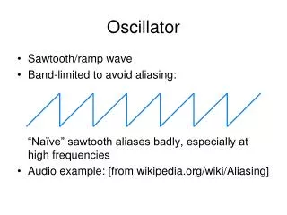
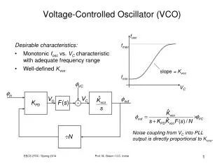
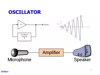
Project Summary • Oscillators are one of the important components in communication systems. They establish transmitter carrier frequency, and drive frequency converters. There are several types of oscillators that are used in commercial and military systems. VCO’s that are tunable to one octave frequency range are available commercially. • It is well known that a distributed amplifier provides very wide bandwidth and high gain. Our design of a VCO will incorporate the distributed amplifier in order to allow a tunable frequency of close to one decade frequency (limited by the transistors). This design approach has never been successfully implemented before.
Previous Work Done • Patents Held: • None Found • Masters Thesis Work: • Sunil Modur Nagabhushana • Graduate Level Work: • Yongqiang He
Standards Applicable • ISM frequency band: • Defined by FCC for general unregulated use: • CFR 47 Part 2 -Frequency Allocations • Standards and Procedures for Microstrip layout and Fabrication: • Variable based upon the fabrication facility • Safety • General usage as per ISM band regulations
Top Level Design Tuning Voltage DC Bias Tunable Bandpass Filter Amplifier Distributed Amplifier Power Divider VCO Output DC Bias
Dane Stivers and Monica Studnicki Distributed Amplifier Power Divider Todd Beyer and Tim MacShane Tunable Bandpass Filter Amplifier Division of Labor
Specifications • Output Frequency Range: 1 to 3 GHz • Design to be tested by operation within the ISM (Industrial, Scientific, Medical) band • Output Power: Stable over whole frequency range • Output Impedance 50 • Tuning Voltage: 0 to 20 V • Biasing Voltage: 15 V DC
Components List • (10 – 12) Discrete Transistors w/ a similar non-linear model as the NE76084S. • Power Divider (PS-2-4000F Wide Band Two Way Combiner/Divider). • (20) Coilcraft 22nH Inductors (0603CS-22NX-BC). • (8-12) Dielectric Laboratories 2400pF DC Blocking Capacitors. • (4) Varactor Diode that has similar operating limits as the MA 46457-186 • (4) Broadband Amplifier (EIC-1019 Broadband Amplifier) • (4) High Frequency Circuit Boards • RO3003 and TMM10i • (12-20) Microstrip Board to Coax Connectors (50 ) • (5) Microstrip Box Mount Coax Connectors (50 ) • Metal Casing for Final Design
Equipment List • Spectrum Analyzer • Network Analyzer • Soldering Iron • Voltage Sources
Facilities Used • The Prototype and Subsystems will be fabricated by us using the fabrication lab on campus. • Bradley University’s machine shop will be utilized for the making if the metal box that the final design will go into. • Also, the final design will be sent outside to a manufacturer (to be determined) to be professionally made.
Software Usage • HP ADS • Mstrip • MATCH • CAMAD
Proposed Schedule • Week 1: • Verify Receipt of Components • Continue Simulations • Week 2: • Verify Components • Continue Simulations • Week 3: • Complete Verification of Components • Start Construction of Subsystems • Weeks 4-9: • Continued Construction of Subsystems • Test Subsystems • Test Interconnected Functionality
Proposed Schedule (Continued) • Week 10: • Construct Prototype • Week 11: • Test Prototype • Weeks 12-14: • Trouble Shooting • Preparation for Expo • Preparation of Final Report