Download
1 / 18
220 likes | 358 Views
Radiometric Correction and Image Enhancement. Modifying digital numbers. Why modify digital numbers (DNs)?. Improve the way an image looks Reduce “noise” in an image Fill in data gaps Normalize digital numbers across a scene (remove effects due to terrain, atmosphere)

E N D
Radiometric Correction and Image Enhancement Modifying digital numbers
Why modify digital numbers (DNs)? • Improve the way an image looks • Reduce “noise” in an image • Fill in data gaps • Normalize digital numbers across a scene (remove effects due to terrain, atmosphere) • Normalize two or more images for multi-temporal comparison • Calculate biophysical values for each pixel (radiance, reflectance, net primary productivity)
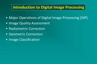
What is radiometric correction? • Radiometric correction attempts to eliminate the effects on a pixel’s value by elements that are not part of the target • These effects are commonly grouped as: • Sensor influences • Terrain effects • Atmospheric effects
Some considerations? • Often a trade-off between benefit derived from the correction and resources (time and money) required to accurately implement the algorithm • Applying a radiometric correction does not necessarily produce accurate results • Good idea to calculate top of the atmosphere reflectance since it is easy and standardizes pixel values to a physical measurement • Using simple correction methods may be sufficient for the task at hand • Always analyze the output from an atmospheric correction application to see if the results make sense
Ideal (laboratory) environment • Clean filtered air • Precise control over detector and illumination source position • Distance light travels from source to detector is short • Precise control over illumination intensity • Sample carefully prepared
Actual environment • Particulates in the atmosphere attenuate the signal (light from the sun) • Terrain and feature structure very complex making it difficult to precisely model the path of light
Different types of radiometric adjustments • Image enhancement • Remove sensor anomalies • Remove illumination/target/detector configuration effects (topographic effects) • Remove atmospheric effects • Remove topographic effects • Calibration - convert digital counts to bio-physical parameters • Normalization – Equalize digital numbers for two or more images
Image enhancement • Goal is to either make the image look nice or to improve interpretability • Uses image scaling, filters, and spectral techniques • Image scaling aims to distribute pixel values across the full range of possible values • Filters are used to increase contrast between different feature or to reduce noise in an image • Spectral transformations synthesize multiple bands into a new band or set of bands • Most image processing software programs have simple tools to apply these enhancements
Sensor anomalies • Line dropout is an occasional problem and can be “fixed” by averaging using data from the line above and below the “bad” line • Sensors are calibrated pre and post-launch • Striping caused by a variable response for different sensors and is less of an issue for modern imagery since it is compensated for on-board the satellite or during initial processing
Illumination/target/detector configuration effects • Goal is to simulate flat terrain so brightly illuminated shadowed areas look similar • An image in rough terrain will look much flatter as shadow effects are reduced • Most approaches use a digital elevation model (DEM) to model the terrain and cosine corrections to correct illumination • Important for the DEM to have similar or finer resolution than the satellite image
Uncorrected Corrected Images from Introductory digital image processing: A remote sensing perspective, John R. Jensen
Atmospheric effects • Atmospheric effects can range from slight to complete obstruction of the intended target (clouds) • Atmospheric effects are often variable across an image • Some approaches (radiative transfer modeling) require atmospheric measurements acquired at the same time as image acquisition (i.e., ATCOR) • Other approaches use only image processing methods and do not require in-situ measurements (i.e., COST)
Calibration • Goal is to convert DN to a biophysical values such as radiance, surface reflectance, or net primary productivity • Calculating at-sensor radiance is often done by the image provider although the calibration coefficients (gain and offset) must be applied by the image user • At-sensor reflectance calculations standardizes illumination geometry and requires that you know the date and time of acquisition (to calculate solar zenith angle), Earth-sun distance and sensor specific data such as solar spectral irradiances • Determining surface reflectance is often very difficult
Normalization • Helpful when comparing imagery from different dates • Matching pseudoinvariant ground targets using regression is a common method • Does not typically compensate for differences between seasons (i.e., wet and dry)
COST algorithm background • An improvement over the dark object subtraction (DOS) method • Incorporates a cosine correction for solar zenith angle • Developed by Pat S. Chavez – USGS • Citation: Chavez, P.S. Jr., 1996, Image-based atmospheric corrections—revisited and revised. Photogrammetric Engineering and Remote Sensing 62(9): 1025-1036.
COST algorithm Where, BandN = Reflectance for Band N GainBandN = Gain for Band N (from Landsat guide) BiasBandN = Bias for Band N (from Landsat guide) LbandN = Digital Number for Band N HbandN = Digital Number representing Dark Object for Band N D = Normalized Earth-Sun Distance EbandN = Solar Irradiance for Band N = Atmospheric Transmittance expressed as
ERDAS implementation of COST • Web site to create ERDAS model (.gmd file) for Landsat TM images: http://www.gis.usu.edu/docs/projects/swgap/ImageStandardization.htm • The model created from the web site above can be opened in the ERDAS “Model Maker” • The Landsat image file must be in NLAPS format with the header (.h1) file • If the image format is not in the NLAPS format an existing model can be manually edited