Download
1 / 15
160 likes | 354 Views
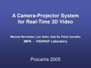
Marcelo Bernardes, Luiz Velho, Asla Sá, Paulo Carvalho IMPA - VISGRAF Laboratory. A Camera-Projector System for Real-Time 3D Video. Procams 2005. Overview. How it works ( b , s )-BCSL code Video + ( b , s )-BCSL code Reconstruction pipeline Snapshots Why it works? Discussions.

E N D
Marcelo Bernardes, Luiz Velho, Asla Sá, Paulo CarvalhoIMPA - VISGRAF Laboratory A Camera-Projector System for Real-Time 3D Video Procams 2005
Overview • How it works • (b,s)-BCSL code • Video + (b,s)-BCSL code • Reconstruction pipeline • Snapshots • Why it works? • Discussions
How it works - Step 1 Projecting and capturing color patterns • Two slides (S1, S2) having vertical color stripes specially coded are projected on the object. Each slide is followed by the projection of its color complement. • A camera captures the four projected patterns on scene. t0 Color slides S1 t1 S1’ t2 S2 Object S2’ t3
- - How it works - Step 2 Camera/projector correspondence • Zero crossings and projected color stripes are robustly identified in camera images using complementary slides. • Projected color sequences are decoded for each zero crossing giving camera/projector correspondence. Zero crossings in camera space + Corresponding stripe boundaries in projector space Zero crossings Projected colors
+ How it works - Step 3 Photometry and geometry reconstruction • Geometry is computed using camera/projector correspondence images and calibration matrices. • Texture image is obtained by a simple combination of each complementary slide pair. For example, the maximum of each channel gives an image that approximates the full white projector light. Reconstructed texture Reconstructed geometry *
(b,s)-BCSL code • The (b,s)-BCSL method defines a coding/decoding procedure for unambiguously finding the number of a stripe transition using s slides and b colors. • In our case, we use b=6 colors (R,G,B,Y,M,C) and s=2 slides which gives two codes of length 900 as illustrated below: • The color transitions R,G in slide 1 and G,C in slide 2 uniquely map to the transition number p in the O(1) decoding procedure. p p-1 p+1 899 1 … … G C Slide 2 color sequence: … … R G Slide 1 color sequence: Slide 2 Stripe transition number = p Slide 1
Video + (b,s)-BCSL code • The key for real time 3D video is the combination of the (b,s)-BCSL code with video stream. • Our scheme has the following features: • A video signal is generated in such a way that each frame contains a slide in the even field the and its complement in the odd field. Frames (S1,S1’) and (S2,S2’) are interleaved in time. • The video signal is sent to both projector and camera. They are synchronized through a genlock signal. • Synchronized camera output is grabbed and pushed into the reconstruction pipeline.
Reconstruction pipeline • Our reconstruction pipeline is as simple as possible achieving real time 3D video with high quality geometry and photometry at 30Hz. This is possible because: • Every input frame captured gives a new texture image (by combining both fields). • New zero crossings and projected color map are computed for every input frame and correlated to the previous frame zero crossings and projected color map. The (b,s)-BCSL decoded transitions give a new geometry set. • The following diagram illustrates the reconstruction pipeline. The frame arrived at time ti gives texture pi from its fields and geometry giby correlation with the frame arrived at time ti-1. 3D Data
Snapshots • The bunny-cube 3D video: Composed virtual scene geometry texture
Snapshots Computed surface normals Moving hand (rendered with lines)
Snapshots • Face and mouth movement
Snapshots • Walking around
Why It works? • Complementary slides projection is suitable for both photometry and geometry detection. • Projected stripe colors are robustly detected through camera/projector color calibration. • Stripe transitions are robustly detected by zero-crossings. • Slides are captured at 60Hz. This is fast enough for capturing “reasonably normal” motion between consecutive frames. • Transition decoding is performed in O(1). • While objects move the stripes projected over their surface remain practically stationary!
Discussion Current System Embodiment uses NTSC video Pros and Cons • Standard off-the-shelf equipment • Widely Available and Good Cost-Benefit • Small resolution • 640x240 per field. (It reduces the maximum number of stripes around 75.) • Composite video signal has poor color fidelity. (It reduces the transition detection precision at stripe boundaries). Solution: High Definition Digital Video.
Alternatives for 3D Video • Technologies • Range Sensors (requires additional camera) • Stereo Methods • Passive Stereo (not robust for real-time) • Active Stereo (needs a projected pattern) • Our system: active stereo with complementary color patterns • Drawback: projector varying light can be uncomfortable for human subjects • Solution: switching complementary slides leads to white light perception as the projection/capture frequency reaches the fusion limit.