Download
1 / 55
550 likes | 666 Views
Acoustic gw detectors: from resonant “bar” to wideband “dual”. Massimo Cerdonio INFN Section and Department of Physics University of Padova, Italy. AURIGA www.auriga.lnl.infn.it DUAL R&D www.dual.lnl.infn.it. Erice June 3 rd 2006. Edoardo AMALDI in Folgaria (Trento) 1989.

E N D
Acoustic gw detectors: from resonant “bar” to wideband “dual” Massimo Cerdonio INFN Section and Department of Physics University of Padova, Italy AURIGA www.auriga.lnl.infn.it DUAL R&D www.dual.lnl.infn.it Erice June 3rd 2006
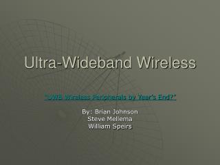
evidence for gravitational waves Emission of gravitational waves Neutron Binary System – Hulse & Taylor PSR 1913 + 16 -- Timing of pulsars 17 / sec · · ~ 8 hr • Neutron Binary System • separated by 106 miles • m1 = 1.4m; m2 = 1.36m; e = 0.617 • Prediction from general relativity • spiral in by 3 mm/orbit • rate of change orbital period
L ~ 103m DL ~ 10-18m h ~ 10-21 (NS/NS @15 Mpc) L-DL L+DL t = 0 t = T /4 t = T/2 t = 3T /4 t = T
Dual Sphere Phys. Rev. Lett. 87 (2001) 031101 ri acoustic gw detectors Single-mass Dual gr-qc/0605004 (2006) Bar Dual Torus Phys. Rev. D 68 (2003) 102004 Antenna pattern: like 2 IFOs co-located and rotated by 45°
VIRGO/LIGO range NS/NS rivelabile a 300 Mpc Adv LIGO/Dual range
physics @ kHz frequencies • Equation Of State of superdense matter • isolated ns deformed pulsars, rotational instabilities, normal modes, “starquakes”, Sn core collapse, accretion spun-up ms pulsars, LowMassXrayBinaries, SoftGammaRay repeaters (flares) • ns-ns binaries “chirp”, bar instabilities, merging, ringdown • Extreme gravity • bh-bh binaries “chirp”, merging, ringdown • Cosmology • stochastic background
Upper limit for burst GWs with random arrival time and measured amplitude search threshold PRL 85 5046 (2000) – Phys. News Upd. 514 Nov. 29 (2000) - PRD 68 022001 (2003) UPPER LIMIT on the RATE of GWburstsfrom the GALACTIC CENTER IGEC-1 results LIGO S2, S3 & S4 improve considerably IGEC-2 will be comparable LIGO S5 will overcome S1 DE ~ 0.02 Msunconverted into gw at the Galactic Center h ~ 2 10-18
bar gw detectors (brief reminder) • how they detect, SQL, bandwidth, antenna pattern • AURIGA recent upgrades • three modes operation to widen the band • approaching the Standard Quantum Limit • suspensions and seismic insulation • how AURIGA performs • AURIGA and the Dec 27th SGR flare
M = 2.3 t L = 3m “bar” gw detectors
“bars” at the Standard Quantum Limit detect few quanta in a 2.3 tons oscillator Eabsorbed ~ hPlanck fbar kBT/Q < hPlanckf • need: • wide detection bandwidth f~100 Hz, large Q/T ~ 108 K-1 • T~ 0.1 K, Q ~ 107 • a quantum limited amplifier: SQUID, optical,… • where are we ? • AURIGA @ 4.5 K Eabsorbed ~ 500 quanta • AURIGA @ 0.1 K Eabsorbrd ~ 10 quanta f~100 Hz Q ~ 5 106 hSQL ~ 3 10-21
AURIGA run II: upgrades • three resonant modes operation: • two mechanical modes • one electrical mode • transducer bias field 8 MV/m • new SQUID amplifier : double stage SQUID ~500 energy resolution at 4.5 K in the detector
Shh sensitivity (2) one-sided Shh Very good agreement with noise predictions all these noise sources will scale with temperature
the three modes of AURIGA as they keep clean and stable in time
AURIGA II run stationary gaussian operation of a wideband “bar” detector • the 3 modes thermal at 4.5 K • Shh1/2 < 4 10-21Hz-1/2 over 90 Hz band (one sided) • ~ 100% operation for acquisition of usable data • (except 3hours/month > He transfer) • veto time intervals under out-of-band triggers to select • against epochs of external disturbances • reduce (for bursts)to stationary gaussian operation over • ~ 96% of time
P.Falferi et al, “3-modes detection…” Phys.Rev.Letters 2005 M.Bonaldi et al,“AURIGA suspensions…” Rev. Sci. Instr. 2005 A.Vinante et al, “Thermal noise in a…” Rev. Sci. Instr. 2005 red: exp blue: sim ~ 4 days of continuous operation SNR duty cycle ~ 96% date
an optomechanical transducer for the AURIGA “bar” gw detector cryogenic optics towards the quantum limit: high finesse cavities, fibers, piezo actuators, etc @ 4.2 K concept and optics: Livia Conti, Maurizio DeRosa, Francesco Marin cryogenics: Michele Bonaldi, Giovanni A. Prodi, Luca Taffarello, Jean-Pierre Zendri
The Dec. 27th 2004 giant flare of the soft gamma ray repeater SGR1806-20 • on a ~ 10 kpc distance scale in the direction of Sagittarium • 100 times more energetic than any other • after peaking with ms rise time, decayed to 1/10 intensity • in ~ 300 ms a catastrophic instability involving global crustal failure in a “magnetar”, which possibly triggers the excitation of f- and p-modes in the neutron star the excited mode damps out by gw emission, the energetics of which would be ~ 100 times larger of that of the X-rays flare
AURIGA and the flare • was optimally oriented towards 1806-20 at the flare time • was performing as a stationary gaussian detector • was covering a ~ 100 Hz band in which neutron star • f- and p-modesmay fall we test if, at the flare time, gw emission is found, as a damped sinusoidal wave train at any frequency f within AURIGA band, with damping time s • divide the band in sub-bands of width f~1/saround each f • integrate for a time t~sthe output energy in the sub-band • check the statistics of the time series (t) in each sub-band f • test for any excess in (t) at the flare peak time tp we take s = 100 ms as ~ 1/3 of the observed flare decay
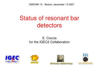
Baggio et al. (AURIGA collaboration)Phys.Rev.Letters 95 081103 (2005) the time origin corresponds to the arrival time of the flare peak tpat the AURIGA site
upper limits on emitted gw energy as fraction of solar mass Over the sub-band at frequency f of width f models predict gw~ 5 10-6
comments on AURIGA & the flare • stationary operation allows relevant searches • even with a single detector • obtained an upper limit about neutron stars • dynamics, which is relevant as it invades part • of the parameter region of existing models • stronger upper limits could be put with optimal • search methods ( I did not discuss this point > see PRL paper)
bar The Concept Optical Transducer Variations of the transducer cavity length are measured by the stabilized laser Transducer cavity: a Fabry-Perot cavity between the bar and the resonant plate Reference cavity: a stable Fabry-Perot cavity acting as length reference Laser source frequency locked to the reference cavity
Optical Transducer Status: Room temperature test Experimental set-up Achieved gw sensitivity L.Conti et al,. Jour. Appl. Phys. 93 (2003) 3589
Status: Cryogenics Optical Transducer Q measurements in the Transducer Test Facility New Cryostat for the bar resonator under construction
[a prototype gw detector in coincidence with AURIGA will operate at 4.2 K ~ 1 year] >>> CANCELED R&D for Dual: optics with high finesse cavities at low T, coating thermal noise and substrate thermoelastic noises (“thermodynamic” and “photothermal”) at levels of displacement ~ 10-20 m/Hz1/2
DUAL how to open wide, many kHz, the band of an acoustic detectors the DUAL R&D collaboration: Firenze, Legnaro, Padova, Trento, Urbino
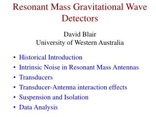
measurement of differential deformations of two oscillators, resonating at different frequencies and both sensitive to the gw signal Dual detector: the concept • Intermediate frequency range: • the slow oscillator is driven above resonance, • the fast oscillator is driven below resonance • phase difference of p differential measurement: signals sum up readout back action noise subtracts out A possible 2D implementation:
the new ideas of the DUAL detector 1 –the “dual” concept :read displacement between two massive resonators (or modes of one mass) with a non-resonant read-outM. Cerdonio et al. Phys. Rev. Lett. 87 031101 (2001); M.Bonaldi et al. (2006) avoid resonant bandwidh limit and thermal noise contribution by the resonant transducer 2 - selective readout:only the motion corresponding to GW sensitive normal modes is measured M. Bonaldi et al. Phys. Rev. D 68 102004 (2003) reduce overall thermal noise by rejecting the contribution of not useful modes
Mode selection strategy Geometrically based mode selection Large interrogation regions Capacitive transducer design Reject high frequency resonant modes which do not carry any GW signal Bandwidth free from acoustic modes not sensitive to GW Also FFP optical scheme F. Marin et.al, Phys. Lett. A 309, 15 (2003) 2-D Quadrupolar filter: X=X1 +X3 –X2 –X4
Dual R&D : 3 main research topics Current technology DUAL requirements Readout system: • mechanical amplification resonant not resonant • 15 x 10x • 100 Hz BW 4 kHz BW • displacement sensitivity • and wide sensing area 5x10 -20 m 5x10-22 (100x) Test masses: • underground operation not necessary define requirements • high cross section ( vs2-3 ) Al 5056 Mo, SiC, Sapph. (50 x) Detector design • seismic noise control external passive embedded active
Readout system for DUAL: mechanical amplification stage • Broadband amplification up to 5.0 kHz • Displacement gain factor about 10 • Negligible intrinsic thermal noise • Compliance H.J. Paik, proceedings First AMALDI Conference (1995) Leverage type amplifier
Mechanical gain measurements direct gain = y/x Leverage behavior Frequency shift
Next step: measure the thermal noise ANSYS Prediction by using Fluctuation Dissipation Theorem Leverage behavior: scaling with gain gain T=300 K, Q=104, Al 7075, w0 =365 m
M3 M1 M4 D M2 Progress towards a wide area optical readout Usual cm-long cavities have small spot size (1mm) higher order acoustic modes of the real system contribute to the noise To average out the noise, we need a spot size > 10cm !!!! Folded Fabry-Perot: FFP F.Marinet alPhys. Lett. A 309, 15 (2003) effective increase of spot size relative shot noise limited displacement sensitivity: constant relative freq. noise due to Brownian noise 1/N relative freq. noise due to rad pressure noise 1/N2 + spatial correlation effects
DUAL is based on a deep revision of the resonant detector design and a R&D on readout systems currently funded by: INFN, EGO, EC (ILIAS) timeline R&D + design : 2006 – 2008 (500 k€) construction: 2009 – 2013 (15 M€- apply to “Ideas” in FP7) FP7 new “Ideas” programme: at last fundamental science (all)…!!! “Enhance the dynamism, creativity and excellence of European research at the frontier of knowledge. <...> Open to proposals from individuals and groups without constraint on size, composition or participation in the projects”