Download
1 / 47
510 likes | 709 Views
Engine Disassembly, Cleaning, and Crack Detection. Use the Proper Disassembly Procedure When an engine is operated, it builds up internal stresses. Even cast iron parts such as cylinder heads can warp if the proper disassembly procedure is not followed.

E N D
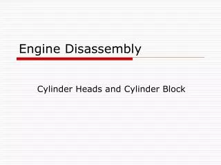
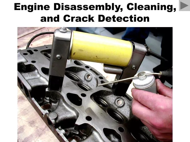
Engine Disassembly, Cleaning, and Crack Detection
Use the Proper Disassembly Procedure • When an engine is operated, it builds up internal stresses. Even cast iron parts such as cylinder heads can warp if the proper disassembly procedure is not followed. • To disassemble any engine without causing harm, just remember these two important points: • Disassemble parts from an engine only after it has been allowed to sit for several hours. • All engines should be disassembled when the engine is at room temperature.
Use the Proper Disassembly Procedure • Always loosen retaining bolts/nuts in the reverse order of assembly. • Most vehicle manufacturers recommend tightening bolts from the center of the component such as a cylinder head toward the outside (ends).
Use the Proper Disassembly Procedure • Therefore, to disassemble the engine, the outside (outer) bolts should be loosened first, followed by bolts closer to the center. • Taking these steps will help reduce the possibility of warpage occurring when the parts are removed.
Engine Disassembly • The piston assemblies must exit the deck side of the block.
Engine Disassembly • The crankshaft should be the last major component removed from the engine. • All camshaft bearings must be removed.
Engine Disassembly • All core plugs and threaded inserts must be removed before the engine is cleaned.
Engine Disassembly • All parts/bolts should be bagged and labeled prior to storage. This is your responsibility!
If the rods and mains are not marked, it is wise to use a punch to make identifying marks before disassembly of the engine. • The orientation of the rods, caps and pistons must also be noted.
Most engines such as this Chevrolet V-8 with 4-bolt main bearing caps have arrows marked on the bearing caps which should point to the front of the engine.
Courtesy of Sealed Power Corporation If the ridge at the top of a cylinder is not removed, the top piston ring could break the second piston ring land when the piston is pushed out of the cylinder during disassembly, or the second piston ring land could break when the engine is first run after reassembly with new rings.
Ridge being removed with one type of ridge reamer before the piston assemblies are removed from the engine.
Puller being used to pull the vibration damper from the crankshaft.
Worn timing chain on a high-mileage engine. Notice that the timing chain could “jump a tooth” at the bottom of the smaller crankshaft gear where the chain is in contact with fewer teeth. Notice also that the technician placed all of the bolts back in the block after removal of the part. This procedure helps protect against loss or damaged bolts and nuts.
This defective cylinder head gasket was discovered as soon as the head was removed. This cylinder head will require machining or replacement.
A torch is used to heat gallery plugs. Paraffin wax is then applied and allowed to flow around the threads. This procedure results in easier removal of the plugs and other threaded fasteners that cannot otherwise be loosened.
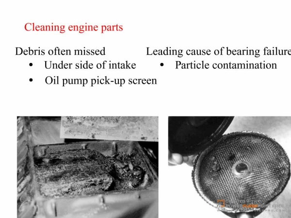
Mechanical Cleaning • Scraping • Putty knife • Used on iron or steel parts • Brass putty knife • Use WITH CAUTION on aluminum parts • Brushing • Use only with iron or steel heads
An air-powered grinder attached to a bristle pad being used to clean the gasket surface of a cylinder head. The color of the bristles indicates the grit number. The white is the finest and should be used on aluminum. Yellow is coarse and can be used on aluminum. Green is designed for cast-iron parts only. This type of cleaning pad should not be used on the engine block where the grit could get into the engine oil and cause harm when the engine is started and run after the repair.
Water-Based Cleaning • Most chemical cleaning is now performed using water-based (aqueous-based) solutions due to environmental concerns. • Most water-based chemicals are now silicate based and mixed with water. • Note: The silicates protect aluminum against corrosion and turning black!
Spray Washing • Faster than soaking • Cycles are generally 30 minutes long • A water-based chemical is heated to 160 - 180 degrees and sprayed onto the parts. • Chemicals must also contain an anti-foaming agent.
A pressure jet washer is similar to a large industrial-sized dishwasher. The part(s) is then rinsed with water to remove chemicals or debris that may remain on the part while it is still in the tank.
Thermal Cleaning • Baking is advantageous because … • It cleans the inside as well as the outside. • The waste generated is non-hazardous. • Best suited for cleaning cast iron. • Parts are baked at temperatures between 666 and 800 degrees. • Aluminum should not be baked over 600 degrees. (cylinder heads over 400 degrees).
Thermal Cleaning (cont.) • A disadvantage of baking is that it leaves a dull and burnt appearance. • A shot blaster is usually used to enhance appearance.
Airless blaster Pyrolytic oven A pyrolytic (high temperature) oven cleans by baking the engine parts. After the parts have been cleaned, they are then placed into an airless blaster. This unit uses a paddle to scoop stainless steel shot from the reservoir and forces it against the engine part. The parts must be free of grease and oil to function correctly.
Blasting • Small solid particles are blasted using compressed air. • Sand • Glass • Steel • Iron • Aluminum
Engine block after being cleaned in a pyrolytic oven and airless blaster.
Airless Blaster • The steel shot from an airless blaster will lodge into any and all holes in an engine block. • For this reason the block must be thoroughly blown out with compressed air. • All threaded holes must be tapped or thread chased!
Small engine parts can be blasted clean in a sealed cabinet.
Chemical Cleaning • Deposits or debris that can be dissolved with a chemical are said to be soluble. • Carbon deposits are removed with chemicals that are said to be caustic. • Caustic materials are highly corrosive, therefore they should be neutralized with water and then air-blown after cleaning.
Chemical Cleaning • Chemicals are classified by a pH value between 1 and 14 • Pure water is neutral and given a value of pH7. • Caustic chemicals are rated between 8 and 14 on the pH scale. The higher the number the higher its causticity. • Acid materials are rated between 1 and 6. The lower the number, the greater the acid property.
Chemical Cleaning Caustics and acids neutralize each other.
Parts Cleaning • Cold tank cleaning • Hot tank cleaning • Vapor cleaning • Vibratory cleaning
Parts Inspection • After parts have been thoroughly cleaned they should be checked for defects. • Visual inspection - dugh
Magnaflux • Magnetic crack inspection • The part is connected to a large electromagnet. • Magnetic lines of force are more concentrated along the edges of a crack. • A fine iron powder is applied to the part, being more concentrated on the edges of a crack. • A brand name • Used on iron or steel parts
If the lines of force are interrupted by a break (crack) in the casting, two magnetic fields are created and the powder will lodge in the crack.
A strong electromagnet can be used to check a cast-iron cylinder head for cracks. The cylinder head should be thoroughly cleaned and placed on a work surface that gives good visibility.
Turn the electromagnet on using the switch at the top and spray a fine iron powder between the poles of the magnet. The magnetic lines of force are more concentrated on the edges of a crack, and the iron powder will be attracted to the strong magnetic concentration around the crack.
Pay particular attention to the area around and between the valve seats.
This cylinder head has cracks running from two valve seats. The head will either have to be replaced or repaired.
This crack in a vintage Ford 289, V-8 block was likely caused by the technician using excessive force trying to remove the plug from the block. The technician should have used heat and wax, not only to make the job easier, but also to prevent damaging the block. Crack
Crack in cylinder wall To make sure that the mark observed in the cylinder wall was a crack, compressed air was forced into the water jacket while soapy water was sprayed on the cylinder wall. Bubbles confirmed that the mark was indeed a crack. Soapy water spray bottle
Pressure Testing • Coolant passages are sealed and compressed air is forced into them. • The component is then lowered into a water tank – air bubbles will appear if a crack is detected.
A cylinder head is under water and being pressure tested using compressed air. Note that the air bubbles indicate a crack.
Dye Penetrate Testing • Used on non-magnetic materials. • A red penetrating chemical is sprayed onto the component and then cleaned. • A white or yellow powder is then applied. • A UV lamp is used to view the part. • staining will occur if a crack is present.
Before welding, the crack is ground out using a carbide grinder. • Here the technician is practicing using the special cast-iron welding torch before welding the cracked cylinder head. • The finished welded crack before final machining. • The finished cylinder head after the crack has been repaired using welding.