Download
1 / 49
490 likes | 726 Views
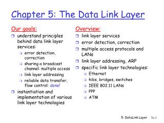
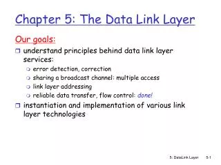
Overview: link layer services error detection, correction multiple access protocols and LANs link layer addressing, ARP specific link layer technologies: Ethernet hubs, bridges, switches IEEE 802.11 LANs PPP. Chapter 5: The Data Link Layer. Our goals:

E N D
Overview: link layer services error detection, correction multiple access protocols and LANs link layer addressing, ARP specific link layer technologies: Ethernet hubs, bridges, switches IEEE 802.11 LANs PPP Chapter 5: The Data Link Layer Our goals: • understand principles behind data link layer services: • error detection, correction • sharing a broadcast channel: multiple access • link layer addressing • reliable data transfer, flow control: done! • instantiation and implementation of various link layer technologies
Link Layer: setting the context • Different link-layer protocols on the different links in the path • Ethernet • Link-layer WAN protocol • PPP Node: Host/Router Network Layer: End-to-End job of moving transport-layer segments from source host to destination host Link-Layer Protocol: Node-to-Node job of moving network-layer datagrams over a single-link in the path
application transport network link physical M H M t H H M n t H H H H H H M M n t l n t l Link Layer: setting the context • two physically connected devices: • host-router, router-router, host-host • unit of data: frame network link physical data link protocol frame phys. link adapter card
Link Layer Services Parallels transport layer services • Framing, link access: • encapsulate datagram into frame, adding header, trailer • implement channel access if shared medium, • ‘physical addresses’ used in frame headers to identify source, destination • different from IP address! • Reliable delivery between two physically connected devices: • we learned how to do this already (chapter 3)! • seldom used on low bit error link (fiber, some twisted pair) • wireless links: high error rates • Q: why both link-level and end-end reliability? Catch the error on the link where it occurs Mechanisms: Seq.Nos, Timers, ACKs
Link Layer Services (more) • Flow Control: • pacing between sender and receivers • Error Detection: • errors caused by signal attenuation & electromagnetic noise. • Sender sets error-detection bits in the frame; receiver detects presence of errors: • signals sender for retransmission or drops frame • Error Correction: • receiver identifies and corrects bit error(s) without resorting to retransmission More sophisticated; hardware-implemented
application transport network link physical M H M t H H M n t H H H H H H M M n t l n t l Link Layer: Implementation Network Interface Card (NIC) • implemented in adapter • e.g., PCMCIA card, Ethernet card • typically includes: RAM, DSP chips, host bus interface, and link interface network link physical data link protocol frame phys. link adapter card
Error Detection EDC= Error Detection and Correction bits (redundancy) D = Data protected by error checking, may include header fields • Error detection not 100% reliable! • protocol may miss some errors, but rarely • larger EDC field yields better detection and correction, but incurs larger overhead
Parity Checking Immediate error correction at the receiver (Forward Error Correction) or FEC Two Dimensional Bit Parity: Detect and correct single bit errors Single Bit Parity: Detect single bit errors Even Parity Scheme Odd Parity Scheme 0 0 Commonly used in Audio storage & playback devices
Receiver: compute checksum of received segment check if computed checksum equals checksum field value: NO - error detected YES - no error detected. But maybe errors nonetheless? More later …. Goal: detect errors (e.g., flipped bits) in transmitted segment (note: used at transport layer only) Internet checksum Software-implemented; requires relatively little packet overhead but weaker protection against errors as compared to CRC Sender: • treat segment contents as sequence of 16-bit integers • checksum: 1's complement of the sum of segment contents • sender puts checksum value into UDP checksum field TCP & UDP computes Internet checksum over all fields
Check summing: Cyclic Redundancy Check Based on CRC codes, also known as polynomial codes • view data bits, D, as a binary number • choose r+1 bit pattern (generator), G with leftmost bit=1 • goal: choose r CRC bits, R, such that • <D,R> exactly divisible by G (modulo 2) • receiver knows G, divides <D,R> by G. If non-zero remainder: error detected! • can detect all burst errors less than r+1 bits • widely used in practice (ATM, HDCL) Multiplication by 2kis thesame as bitpattern << k
Given: D=101110, d=6, G=1001, r=3 Output: transmitted=101110011 1011 0101 1110 CRC Example Done in modulo-2 arithmetic without carries in addition or borrows in subtraction (XOR) Want: D.2r XOR R = nG equivalently: D.2r = nG XOR R equivalently: if we divide D.2r by G, want reminder R D.2r G R = remainder[ ] We are interested only in the remainder.
Multiple Access Links and Protocols Two types of network links: • Point-to-point link (single wire, e.g. PPP, SLIP) • Broadcast link (shared wire or wireless medium; e.g, Ethernet, Wavelan, etc.)
Multiple Access protocols (MAC) Regulates node transmission over shared broadcast channel • single shared communication channel • two or more simultaneous transmissions by nodes: interference • only one node can send successfully at a time • multiple access protocol: • distributed algorithm that determines how stations share channel, i.e., determines when the station can transmit • communication about channel sharing must use channel itself! • what to look for in multiple access protocols: • synchronous or asynchronous • information needed about other stations • robustness (e.g., to channel errors) • performance
MAC Protocols: a taxonomy Three broad classes: • Channel Partitioning Protocols • divide channel into smaller pieces (time slots, frequency bands, multiple access codes) • allocate piece to node for exclusive use • Random Access Protocols • allow collisions • recover from collisions • Taking turns Protocols • tightly coordinate shared access to avoid collisions Animation
MAC Protocols Goal: efficient, fair, simple, decentralized DESIRABLE CHARACTERISTICS For a broadcast channel of R bps: • For only one sending node: throughput = R bps • For M sending nodes: throughput = R/M bps • not instantaneous transmission rate, but average transmission rate of R/M bps over some suitably defined time interval • Decentralized • Simple, inexpensive to implement
Channel Partitioning MAC protocols: TDMA Divide time into Frames, and further divide Frames into N time slots TDMA: Time Division Multiple Access • access to channel in rounds • each station gets fixed length slot (length = pkt trans time) in each round • Drawback: unused slots go idle • example: 6-station LAN, 1,3,4 have pkt, slots 2,5,6 idle • TDM (Time Division Multiplexing): channel divided into N time slots, one per user • Advantages: eliminates collision; perfectly fair; dedicated transmission rate of R/N • Disadvantage: inefficient with low duty cycle users and at light load. See more slides
Channel Partitioning MAC protocols: FDMA: Frequency Division Multiple Access channel spectrum divided into frequency bands • each station assigned fixed frequency band • Drawback: • Unused transmission time in frequency bands go idle • Node is limited to a bandwidth of R/N, even when all the other nodes are idle at the time • example: 6-station LAN, 1,3,4 have pkt, frequency bands 2,5,6 idle • FDM (Frequency Division Multiplexing): frequency subdivided. time Divide channel of R bps into different Frequencies (each with R/N), and assign each Frequency to one of the nodes N See more slides frequency bands
TDM & FDM Suppose that a channel supports N nodes, with transmission rate of R bps DRAWBACKS • A NODE is limited to a bandwidth of R/N when it is the only node with packets to send • (Only for TDM) A NODE must always wait for its turn in the transmission sequence, even when it is the only node with a packet to send
Random Access protocols • When node has packet to send • transmit at full rate (R) of channel • no a priori coordination among nodes • two or more transmitting nodes -> collision!!, • random access MAC protocol specifies: • how to detect collisions • how to recover from collisions (e.g., via delayed retransmissions) • Examples of random access MAC protocols: • slotted ALOHA • ALOHA • CSMA and CSMA/CD
CSMA: (Carrier Sense Multiple Access) CSMA: listen before transmit: • If channel sensed idle: transmit entire pkt • If channel sensed busy, defer transmission • Persistent CSMA: retry immediately with probability p when channel becomes idle (may cause instability) • Non-persistent CSMA: retry after random time interval • human analogy: don't interrupt others! • RULES: • Listen before speaking (carrier sensing) • If someone else begins talking at the same time, stop talking (collision detection) Animation
Channel propagation delay CSMA collisions 4 nodes attached to a linear broadcast bus; Horizontal axis shows position of each node in space spatial layout of nodes along ethernet collisions can occur: propagation delay means two nodes may not yet hear each other's transmission collision: entire packet transmission time wasted D senses the channel is idle at t1 note: role of distance and propagation delay in determining collision prob.
CSMA/CD (Collision Detection) CSMA/CD: carrier sensing, deferral as in CSMA • collisions detected within short time • colliding transmissions aborted, reducing channel wastage • persistent or non-persistent retransmission • collision detection: • easy in wired LANs: measure signal strengths, compare transmitted, received signals • difficult in wireless LANs: receiver shut off while transmitting • human analogy: the polite conversation
CSMA/CD collision detection 4 nodes attached to a linear broadcast bus
Slotted Aloha • time is divided into equal sized slots (= pkt trans. time) • node with new arriving pkt: transmit at beginning of next slot • if collision: retransmit pkt in future slots with probability p, until successful. Success (S), Collision (C), Empty (E) slots
Slotted Aloha efficiency Q: what is max fraction of slots that are successful? A: Suppose N stations have packets to send • each transmits in slot with probability p • prob. successful transmission S is: by single node: S= p (1-p)(N-1) by any of N nodes S = Prob (only one transmits) = N p (1-p)(N-1) … choosing optimum p as n -> infinity ... Maximum Efficiency of Protocol = 1/e = .37 as N -> infinity At its best: channel use for successful transmissions is 37% of the time! Find p that maximizes the expression e.g. For a network with 100 Mbps Slotted ALOHA system, the successful throughput < 37Mbps.
Pros single active node can continuously transmit at full rate of channel highly decentralized: only slots in nodes need to be in sync simple Cons collisions, wasting slots idle slots nodes may not be able to detect collision in less than time to transmit packet clock synchronization Slotted ALOHA
Pure (unslotted) ALOHA FULLY DECENTRALIZED PROTOCOL • unslotted Aloha: simpler, no synchronization • If pkt needs transmission: • sends immediately without waiting for the beginning of slot • If there’s a collision after transmission: • Retransmit frame with probability p Else Wait for next transmission time • Collision probability increases: • pkt sent at t0 collide with other pkts sent in [t0-1, t0+1]
0.4 0.3 protocol constrains effective channel throughput! Slotted Aloha 0.2 0.1 Pure Aloha 1.5 2.0 0.5 1.0 G = offered load = Np Pure Aloha (cont.) P(success by given node) = P(node transmits a frame) . P(no other node transmits in [t0-1,t0] . P(no other node transmits in [t0, t0+1] = p . (1-p)(N-1) . (1-p)(N-1) P(success by any of N nodes) = N p . (1-p) 2(N-1) … choosing optimum p as n -> infinity ... = 1/(2e) = .18 S = throughput = “goodput” (success rate)
Channel Partitioning (CDMA) CDMA (Code Division Multiple Access) • Sender: sends encoded data bits simultaneously • Receiver: assigned a unique code (i.e. code set partitioning) • Has been used by military; now used mostly in wireless broadcast channels (cellular, satellite,etc) • all users share same frequency, but each user has own ''chipping'' sequence (i.e., code) to encode data • encoded signal = (original data) X (chipping sequence) • decoding: inner-product of encoded signal and chipping sequence • Advantage: allows multiple users to coexist and transmit simultaneously with minimal interference (if codes are orthogonal)
CDMA Encode/Decode M mini slots are assigned to each data bit
CDMA: two-sender interference Assumption: interfering bit signals are additive
Taking Turns MAC protocols channel partitioning MAC protocols: • share channel efficiently at high load • inefficient at low load: delay in channel access, R/N bandwidth allocated even if only 1 active node! Random access MAC protocols • efficient at low load: single node can fully utilize channel • high load: collision overhead taking turns protocols look for best of both worlds!
Token passing: • control tokenpassed from one node to next sequentially. • token message • concerns: • token overhead • latency • single point of failure (token) Taking Turns MAC protocols Polling: • master node invites slave nodes to transmit in turn • Request to Send, Clear to Send msgs • concerns: • polling overhead • latency • single point of failure (master) e.g. FDDI, IEEE 802.5 Animation
Reservation-based protocols Distributed Polling: • time divided into slots • begins with N short reservation slots • reservation slot time equal to channel end-end propagation delay • station with message to send posts reservation • reservation seen by all stations • after slot reservation, message transmissions are ordered by known priority • Nodes can transmit only up to a max number of frames
Summary of MAC protocols • What do you do with a shared media? • Channel Partitioning, by time, frequency or code • Time Division,Code Division, Frequency Division • Random partitioning (dynamic), • ALOHA, S-ALOHA, CSMA, CSMA/CD • carrier sensing: easy in some technologies (wire), hard in others (wireless) • CSMA/CD used in Ethernet • Taking Turns • polling from a central site, token passing
LAN technologies Data link layer so far: • services, error detection/correction, multiple access Next: LAN technologies • addressing • Ethernet • hubs, bridges, switches • 802.11
LAN Addresses and ARP Recall 32-bit IP address: • network-layer address • used to get datagram to destination network (recall IP network definition) LAN or Media Access Control (MAC) or physical address: • used to get datagram from one interface to another physically-connected interface (same network) • 48 bit MAC address (for most LANs) burned in the adapter ROM
LAN Addresses and ARP Each adapter on LAN has unique LAN address
LAN Address (more) • MAC address allocation administered by IEEE • manufacturer buys portion of MAC address space (to assure uniqueness) • Analogy: (a) MAC address: like Social Security Number (b) IP address: like postal address • MAC flat address => portability • can move LAN card from one LAN to another • IP hierarchical address NOT portable • depends on network to which one attach to
Starting at A, given IP datagram addressed to B: • look up net. address of B, find B on same net. as A • link layer send datagram to B inside link-layer frame A 223.1.1.1 223.1.2.1 223.1.1.2 223.1.2.9 223.1.1.4 B 223.1.2.2 E 223.1.3.27 223.1.1.3 223.1.3.2 223.1.3.1 Recall earlier routing discussion frame source, dest address datagram source, dest address A’s IP addr B’s IP addr A’s MAC addr B’s MAC addr IP payload datagram frame
Question: how to determine MAC address of B given B's IP address? ARP: Address Resolution Protocol • Each IP node (Host, Router) on LAN has an ARP module, table • ARP Table: IP/MAC address mappings for some LAN nodes < IP address; MAC address; TTL> < ………………………….. > • TTL (Time To Live): time after which address mapping will be forgotten (typically 20 min) We have an example later
ARP protocol We have an example later • A knows B's IP address, wants to learn physical address of B • A broadcasts ARP query pkt, containing B's IP address • all machines on LAN receive ARP query • B receives ARP packet, replies to A with its (B's) physical layer address • A caches (saves) IP-to-physical address pairs until information becomes old (times out) • soft state: information that times out (goes away) unless refreshed
Routing to another LAN routing from A to B via R • In the routing table at source Host, A finds router 111.111.111.110 • In ARP table at source, find MAC address E6-E9-00-17-BB-4B, etc A R B
A creates IP packet with source A, destination B • A uses ARP to get R's physical layer address for 111.111.111.110 • A creates Ethernet frame with R's physical address as dest, Ethernet frame contains A-to-B IP datagram • A's data link layer sends Ethernet frame • R's data link layer receives Ethernet frame • R removes IP datagram from Ethernet frame, sees its destined to B • R uses ARP to get B's physical layer address • R creates frame containing A-to-B IP datagram sends to B A R B
DHCP: Dynamic Host Configuration Protocol Goal: allow host to dynamically obtain its IP address from network server when it joins network Can renew its lease on address in use Allows reuse of addresses (only hold address while connected and “on” Support for mobile users who want to join network (more shortly) DHCP overview: • host broadcasts “DHCP discover” msg • DHCP server responds with “DHCP offer” msg • host requests IP address: “DHCP request” msg • DHCP server sends address: “DHCP ack” msg
E B A DHCP client-server scenario 223.1.2.1 DHCP 223.1.1.1 server 223.1.1.2 223.1.2.9 223.1.1.4 223.1.2.2 arriving DHCP client needs address in this network 223.1.1.3 223.1.3.27 223.1.3.2 223.1.3.1
DHCP discover src : 0.0.0.0, 68 dest.: 255.255.255.255,67 yiaddr: 0.0.0.0 transaction ID: 654 DHCP client-server scenario arriving client DHCP server: 223.1.2.5 DHCP offer src: 223.1.2.5, 67 dest: 255.255.255.255, 68 yiaddrr: 223.1.2.4 transaction ID: 654 Lifetime: 3600 secs DHCP request src: 0.0.0.0, 68 dest:: 255.255.255.255, 67 yiaddrr: 223.1.2.4 transaction ID: 655 Lifetime: 3600 secs time DHCP ACK src: 223.1.2.5, 67 dest: 255.255.255.255, 68 yiaddrr: 223.1.2.4 transaction ID: 655 Lifetime: 3600 secs