Download
1 / 19
210 likes | 394 Views
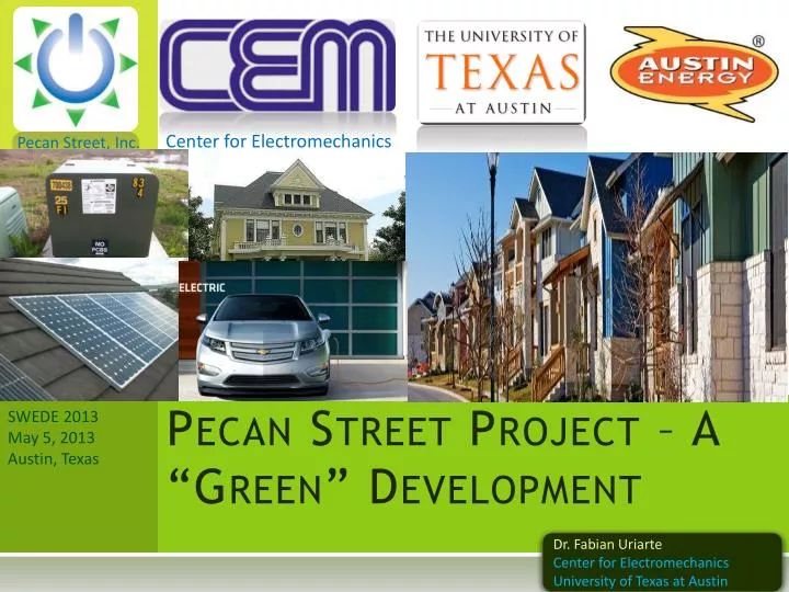
Center for Electromechanics. Pecan Street, Inc. Pecan Street Project – A “Green” Development. SWEDE 2013 May 5 , 2013 Austin, Texas. Dr. Fabian Uriarte Center for Electromechanics University of Texas at Austin. Smart Grid Location. Pecan Street offices. Texas Advanced Computing Center.

E N D
Center for Electromechanics Pecan Street, Inc. Pecan Street Project – A “Green” Development SWEDE 2013 May 5, 2013 Austin, Texas Dr. Fabian Uriarte Center for Electromechanics University of Texas at Austin
Smart Grid Location Pecan Street offices Texas Advanced Computing Center Ctr. for Electromechanics pecanstreet.org Mueller Community
Transformer Load* Circuit feed (7.2 kV) Homes per transformer: Maximum: 11 Mode: 8 Minimum: 4 20-40 xfms. 240/120V *One possible combination
Load Distribution by Phase (Photovoltaic Arrays) (Electric Vehicles)
Case Study Center for Electromechanics * Modeling in progress
Simulation Approach • Grow
Residential Load Real Data
PV Generation Real Data 0.5 - 1 MW of distributed PV generation daily
EV Load Mix of 120 V and 240 V charging > 4 PM
Transformer Utilization Before PVs and EVs After PVs and EVs • High PV/Load ratio causes reverse flows • Can increase or decrease xfm. utilization
Change in Transformer Load No change • Example (blue areas): • Usage before: 25 % (fwd. direction) • Usage after: 5 % (reverse direction) • Change: 20 % • “-” or “<0” shows reduction in utilization • “>0” means increase in utilization PVs produce 23% increase EVs produce 2% increase
Lateral Power As seen from here Before PVs and EVs After PVs and EVs PF PF VA VA Watts Watts Vars Vars • 0.5 MW reduction in real power demand • Equal reactive power demand • Power factor drops
Lateral Current From here Before PVs and EVs After PVs and EVs • Decrease in diurnal current unbalance • Peak time unbalance unchanged
Distribution Losses Before PVs and EVs After PVs and EVs Increase due to EVs Reduction due to PVs Xfmlosses almost unchanged $45/day = $16k/year
Conclusions Center for Electromechanics • Simulation Model • We have real data (1 m resolution ) • Consumption • PV generation • Can simulate entire smart grid (735 homes) • Confidence in results • Transformers • Appear oversized already • Some operate ~80% • Can meet EV load (at Mueller community) • Power flow is forwards and backwards • Residential Solar Panels (PVs) • Inject power back into the grid • Injection is uncontrolled and unbalanced • Reduce lateral and transformer power factor • Provide voltage support • Electric Vehicles (Chevy Volts) • Uncontrolled charging exacerbates peak demand • Electrical impact appears small due to transformer sizing
Questions Center for Electromechanics Fabian Uriarte f.uriarte@cem.utexas.edu Center for ElectromechanicsThe University of Texas at Austin utexas.edu/research/cem 10100 Burnet Road, Austin, TX


![Six Sigma [Green Belt Project]](https://cdn0.slideserve.com/646243/six-sigma-green-belt-project-dt.jpg)