Download
1 / 20
200 likes | 330 Views
Localization of Piled Boxes by Means of the Hough Transform. Dimitrios Katsoulas Institute for Pattern Recognition and Image Processing University of Freiburg. Introduction. Depalletizing : automatic unloading of piled objects via a robot. How important a solution to the problem is?

E N D
Localization of Piled Boxes by Means of the Hough Transform Dimitrios Katsoulas Institute for Pattern Recognition and Image Processing University of Freiburg
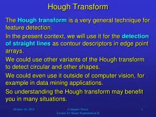
Introduction • Depalletizing: automatic unloading of piled objects via a robot. • How important a solution to the problem is? • We deal with objects most frequently encountered: Boxes, box-like objects (e.g. sacks full of material) • Applications: Post, distribution centers, airports. • Here: Boxes of unknown dimensions.
Existing Systems • Intensity cameras are utilized. • Based on detection of markers on the exposed surfaces of the objects. • Advantages: Computational efficiency • Disadvantages: • Markers do not always exist! • Systems deal only with neatly placed configurations of objects of the same dimensions. • Performance depends on lighting conditions at installation sites.
Our approach • Question: How can we recover the fully exposed surfaces (graspable surfaces) of the objects from input range images?
Recovery of graspable surfaces • Fully exposed object surfaces: Planar surfaces with rectangle boundaries. • Hypothesis generation (Edge based): Recover rectangle boundaries of the graspable surfaces. • Hypothesis verification (Region based): Examine if the range points inside the hypothesized boundaries lie on the plane defined by the boundary.
Hypothesis generation • Rectangle boundaries: Geometric parametric entities with 8 parameters: (6 pose parameters and 2 dimension parameters). • Tool for recovery of multiple parametric entities from images: Hough transform (HT). • Problems of HT: Computationally inefficient, memory consuming, not robust. • Proposed solution: Decompose the problem into simpler sub-problems, use the HT to solve each: • Recovery of the pose. • Recovery of the dimensions.
Pose recovery • [Chen.Kak:89]: A visible vertex of a convex object provides the strongest constraints for accurately determining its pose. • Vertex detection technique: • Detect 3D object boundary lines via HT. • Group orthogonal pairs of lines to vertices. • Vertex representation: • Two boundary lines joining at the vertex point. • The intersection point of those boundaries. • Pose estimation: via alignment.
Line detection in Range Images • Perform edge detection on input range image. • Find 3D lines in the edge map by problem decomposition: • Recover the 4 line parameters by solving 2 2D subproblems each recovering 2 line parameters Computational efficiency. • Constrain the Hough transform to lie on an 1D curve Robustness, low memory consumption.
Problems of vertex detection • Not all the linear boundaries and as consequence not all the vertices of the exposed surfaces were recovered! • Reason: Lines passing from randomly selected points (distinguished points) are recovered computational efficiency. • Disadvantages: Some of the boundary lines are not recovered. • Side effect: Object dimensions cannot be derived from vertices only. • Solution: Derive dimensions from boundary points.
Recovery of dimensions (1) • Dimensions: Determined from the pose parameters + the edge points. • Candidate edge points: • On the same plane with a detected vertex. • On the first quadrant of the coordinate system defined by the vertex.
Verification • Until now we have managed to recover rectangle boundaries from images. • Question: Do those boundaries correspond to boundaries of graspable surfaces? • Answer: Derived from the range points inside the boundaries. • Verification: Check if the range points inside a recovered boundary belong to the plane defined by the boundary.
Statistical tests: Avoid thresholds. • Multiple decisions which have to be based on thresholds: • Group lines forming an angle of 90 degrees. • Determine if image points belong to a given plane. • Thresholds: difficult to set, depends on the application and on the uncertainty in calculation of line parameters. • Can we avoid multiple thresholds? Yes, by introducing statistical tests. All thresholds are replaced by a unique significance value. • We adopt the framework of [Foerstner et.al:00] for its compactness and straightforwardness.
Experimental results • Computational efficiency(on a Pentium 3 600 MHz): • Scanning: 6.5 sec • Edge detection: 2 sec • Hypothesis generation + verification: 8 sec. • Overall: ~ 17 sec. • Accuracy: • < 2.5 cm translational accuracy. • < 2degrees rotational accuracy. • Robustness: • No false alarms. • The system only occasionally fails to recover all the graspable surfaces in the pile.
Conclusions • Advantages: • Insensitivity to lighting conditions: Usage of laser sensor. • Accuracy: Accurate calculation of pose parameters. • Robustness: Decisions based both on edge and region based information, statistical tests are employed. • Computational efficiency: Parameter recovery problem decomposition into smaller sub-problems. • Versatility: Deals with both jumbled and neat object configurations. • Simplicity. • Problems: • Height of objects not recovered. • System fails when no boundary information can be recovered, that is when the distance between neighbouring objects is smaller than the sensor resolution.
Do you want to know how we deal with those objects?... • Come to ICCV 03!