Download
1 / 23
230 likes | 401 Views
ELECTRON AND ION ENERGY DISTRIBUTIONS IN 2-FREQUENCY CAPACITIVELY COUPLED PLASMA TOOLS CONSIDERING WAVE EFFECTS* Yang Yang a) and Mark J. Kushner b) a) Department of Electrical and Computer Engineering Iowa State University, Ames, IA 50011, USA yangying@iastate.edu

E N D
ELECTRON AND ION ENERGY DISTRIBUTIONS IN 2-FREQUENCY CAPACITIVELY COUPLED PLASMA TOOLS CONSIDERING WAVE EFFECTS* Yang Yanga) and Mark J. Kushnerb) a)Department of Electrical and Computer Engineering Iowa State University, Ames, IA 50011, USA yangying@iastate.edu b)Department of Electrical Engineering and Computer Science University of Michigan, Ann Arbor, MI 48109, USA mjkush@umich.edu http://uigelz.eecs.umich.edu October 2008 * Work supported by Semiconductor Research Corp., Applied Materials and Tokyo Electron Ltd. YY_MJK_GEC2008_01
University of Michigan Institute for Plasma Science and Engineering AGENDA • Introduction to wave effects in 2-frequency capacitively coupled plasma (2f-CCP) sources • Description of the model • Scaling of 2f-CCPs in Ar/CF4 mixture with • High frequency (HF) • Low frequency (LF) power • Concluding remarks YY_MJK_GEC2008_02
University of Michigan Institute for Plasma Science and Engineering WAVE EFFECTS IN hf-CCP SOURCES • Wave effects in CCPs become important with increasing frequency and wafer size. • Wave effects (i.e., propagation, constructive and destructive interference) can significantly affect the spatial distribution of power deposition and reactive fluxes. G. A. Hebner et al, Plasma Sources Sci. Technol., 15, 879(2006) YY_MJK_GEC2008_03
University of Michigan Institute for Plasma Science and Engineering GOALS OF THE INVESTIGATION • Relative contributions of wave and electrostatic edge effects determine plasma distribution. • Plasma distribution ultimately depends on • How electrons are accelerated by electric fields • Electron energy distributions • Electron impact reactions with feedstock gases and their fragments. • In this talk, results from a computational investigation of plasma properties in two-frequency CCPs will be discussed : • Spatial variation of electron energy distributions (EEDs) • Radial variation of ion energy and angular distributions (IEADs) onto wafer YY_MJK_GEC2008_04
University of Michigan Institute for Plasma Science and Engineering METHODOLOGY OF THE MAXWELL SOLVER • Full-wave Maxwell solvers are challenging due to coupling between electromagnetic (EM) and sheath forming electrostatic (ES) fields. • EM fields are generated by rf sources and plasma currents while ES fields originate from charges. • We separately solve for EM and ES fields and sum for plasma transportation. • Compatible boundary conditions (BCs) defined for EM and ES fields: • BCs for EM field: Determined by rf sources. • BCs for ES field: Determined by blocking capacitor (DC bias) or applied DC voltages. YY_MJK_GEC2008_05
University of Michigan Institute for Plasma Science and Engineering THE FIRST PART: EM SOLUTION • Launch rf fields where power is fed into the reactor. • For cylindrical geometry, TM mode gives Er , Ez and H . • Solve EM fields using FDTD techniques with Crank-Nicholson scheme on a staggered mesh: • Mesh is sub-divided for numerical stability. YY_MJK_GEC2008_06
University of Michigan Institute for Plasma Science and Engineering THE SECOND PART: ES SOLUTION • Solve Poisson’s equation semi-implicitly: • Boundary conditions on metal: self generated DC bias by plasma or applied DC voltage. • Implementation of this solver: • Specify the location that power is fed into the reactor. • Addressing multiple frequencies in time domain for arbitrary geometry. • First order BCs for artificial or nonreflecting boundaries (i.e., pump ports, dielectric windows). YY_MJK_GEC2008_07
Electron Energy Transport Module Te,S,μ E, N Fluid Kinetics Module Fluid equations (continuity, momentum, energy) Maxwell Equations Plasma Chemistry Monte Carlo Module University of Michigan Institute for Plasma Science and Engineering HYBRID PLASMA EQUIPMENT MODEL (HPEM) • Electron Energy Transport Module: • Electron Monte Carlo Simulation provides EEDs of bulk electrons • Separate MCS used for secondary, sheath accelerated electrons • Fluid Kinetics Module: • Heavy particle and electron continuity, momentum, energy • Maxwell’s Equation • Plasma Chemistry Monte Carlo Module: • IEADs onto wafer YY_MJK_GEC2008_08
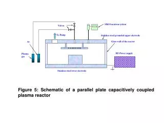
University of Michigan Institute for Plasma Science and Engineering REACTOR GEOMETRY • Main species in Ar/CF4 mixture • Ar, Ar*, Ar+ • CF4, CF3, CF2, CF, C2F4, C2F6, F, F2 • CF3+, CF2+, CF+, F+ • e, CF3-, F- • 2D, cylindrically symmetric. • Ar/CF4 = 90/10, 50 mTorr, 400 sccm • Base conditions • HF upper electrode: 10-150 MHz, 300 W • LF lower electrode: 10 MHz, 300 W • Specify power, adjust voltage. YY_MJK_GEC2008_09
University of Michigan Institute for Plasma Science and Engineering AXIAL EM FIELD IN HF SHEATH • HF = 50 MHz, Max = 410 V/cm • Ar/CF4=90/10, 50 mTorr, 400 sccm • HF: 10-150 MHz/300 W • LF: 10 MHz/300 W • HF = 150 MHz, Max = 355 V/cm • |Ezm| = Magnitude of axial EM field’s first harmonic at HF. • No electrostatic component in Ezm: purely electromagnetic. • 150 MHz: center peaked due to constructive interference of plasma shortened wavelengths. • 50 MHz: Small edge peak. YY_MJK_GEC2008_10
University of Michigan Institute for Plasma Science and Engineering AXIAL E-FIELD IN HF AND LF SHEATH: 10/150 MHz • ANIMATION SLIDE-GIF • |EZ| in HF (150 MHz) Sheath, Max = 1500 V/cm • |EZ| in LF(10 MHz) Sheath, Max = 1700 V/cm • Significant change of |Ez| across HF sheath as evidence of traveling wave. • HF source also modulates E-field in LF sheath. • Ar/CF4=90/10 • 50 mTorr, 400 sccm • HF: 150 MHz/300 W • LF: 10 MHz/300 W YY_MJK_GEC2008_11a
University of Michigan Institute for Plasma Science and Engineering LF CYCLE AVERAGED AXIAL E-FIELD IN HF AND LF SHEATH: 10/150 MHz • |EZ| in HF (150 MHz) Sheath, Max = 450 V/cm • |EZ| in LF(10 MHz) Sheath, Max = 750 V/cm • Significant change of |Ez| across HF sheath as evidence of constructive interference. • Ar/CF4=90/10 • 50 mTorr, 400 sccm • HF: 150 MHz/300 W • LF: 10 MHz/300 W YY_MJK_GEC2008_11b
EEDs IN HF SHEATH 1 2 3 University of Michigan Institute for Plasma Science and Engineering • Ar/CF4=90/10 • 50 mTorr, 400 sccm • HF: 10-150 MHz/300 W • LF: 10 MHz/300 W • 1 : r = 0.3 cm • 2 : r = 7.5 cm • 3 : r = 15 cm • 50 MHz • 150 MHz • 150 MHz: elevated EEDs in the center where sheath field is largest. • 50 MHz: populated tails for r 7 cm due to edge effect. • From 150 MHz to 50 MHz: 2 temperature distribution transits to 1 temperature distribution. YY_MJK_GEC2008_12
EEDs IN LF SHEATH 1 2 3 University of Michigan Institute for Plasma Science and Engineering • Ar/CF4=90/10 • 50 mTorr, 400 sccm • HF: 10-150 MHz/300 W • LF: 10 MHz/300 W • 1 : r = 0.3 cm • 2 : r = 7.5 cm • 3 : r = 15 cm • 150 MHz • 50 MHz • HF modulation extends to the LF sheath at 150 and 50 MHz. YY_MJK_GEC2008_13
EEDs IN BULK PLASMA 1 2 3 University of Michigan Institute for Plasma Science and Engineering • Ar/CF4=90/10 • 50 mTorr, 400 sccm • HF: 10-150 MHz/300 W • LF: 10 MHz/300 W • 1 : r = 0.3 cm • 2 : r = 7.5 cm • 3 : r = 15 cm • 150 MHz • 50 MHz • 150 MHz: does not show strong radial variation. • 50 MHz: edge effect affects EEDs in the bulk plasma. YY_MJK_GEC2008_14
ELECTRON AND NEGATIVE IONS DENSITY: Ar/CF4 = 90/10 University of Michigan Institute for Plasma Science and Engineering • [e] • [CF3-+ F-] • Spatial variation of EEDs translates to plasma uniformity through electron impact reactions. • 100 MHz: [e] is edge peaked. • 150 MHz: [CF3-+ F-] peaked in the center and flattens local plasma potential, so [e] escaping from the center and peaked at r = 9.5 cm. • Ar/CF4=90/10 • 50 mTorr, 400 sccm • HF: 10-150 MHz/300 W • LF: 10 MHz/300 W YY_MJK_GEC2008_15
ION FLUXES INCIDENT ON WAFER University of Michigan Institute for Plasma Science and Engineering • Total Ion Flux • CF3+ Flux • Plasma spatial distribution determines local sheath thickness, potential and ion mixing ratio… • Thereby determining radial uniformity of ion fluxes and their IEADs onto wafer. • Relative uniform fluxes at 100 MHz. • HF: 10-150 MHz/300 W • LF: 10 MHz/300 W • Ar/CF4=90/10 • 50 mTorr, 400 sccm YY_MJK_GEC2008_16
TOTAL ION IEADs INCIDENT ON WAFER University of Michigan Institute for Plasma Science and Engineering Center Edge • IEADs are separately collected over center&edge of wafer. • Radial non-uniformity increases from 100 MHz to 150 MHz. • Results from increasing radial variation of sheath thickness, potential... • HF=150 MHz • HF=100 MHz • Center • Center • Edge • Edge • Ar/CF4=90/10, 50 mTorr, 400 sccm • HF: 150 MHz/300 W • LF: 10 MHz/300 W YY_MJK_GEC2008_17
EFFECT OF LF POWER ON EEDS IN HF SHEATH: 10/150 MHz University of Michigan Institute for Plasma Science and Engineering • LF: 1500 W • LF: 300 W • 1 : r = 0.3 cm • 2 : r = 7.5 cm • 3 : r = 15 cm • Increasing LF power increases [e] and so shortens plasma wavelength. • Strengthens finite wavelength effect and so gives large sheath potential in the center. • Results in more prominent tails for local EEDs. • HF: 150 MHz/300 W • LF: 10 MHz • Ar/CF4=90/10 • 50 mTorr, 400 sccm YY_MJK_GEC2008_18
ELECTRON IMPACT IONIZATION SOURCE FUNCTION: 10/150 MHz • LF: 300 W, Max = 3.9 x 1016 cm-3s-1 • Source from bulk and secondary electrons. • LF power mainly enhances bulk ionization. • Contribution to ionization from electrons accelerated by HF sheath is still significant at 1500 W. • LF: 1500 W, Max = 3.3 x 1016 cm-3s-1 • HF: 150 MHz/300 W • LF: 10 MHz • Ar/CF4=90/10 • 50 mTorr, 400 sccm University of Michigan Optical and Discharge Physics YY_MJK_GEC2008_19
SCALING WITH LF POWER: 10/150 MHz University of Michigan Institute for Plasma Science and Engineering • [e] • [CF3-+ F-] • With increasing LF power • More energetic electrons are available in the HF sheath, thereby enhancing ionization in the center. • [e] becomes increasingly center enhanced, which increases plasma non-uniformity. • HF: 50-150 MHz/300 W • LF: 10 MHz • Ar/CF4=90/10 • 50 mTorr, 400 sccm YY_MJK_GEC2008_20
TOTAL ION IEADs INCIDENT ON WAFER University of Michigan Institute for Plasma Science and Engineering Center Edge • Increasing LF power increases plasma non-uniformity. • As such, radial uniformity of sheath thickness and potential decreases. • Translates to non-uniformity of IEADs across wafer. • 300 W • 1500 W • Center • Center • Edge • Edge • Ar/CF4=90/10, 50 mTorr, 400 sccm • HF: 150 MHz/300 W • LF: 10 MHz YY_MJK_GEC2008_21
CONCLUDING REMARKS University of Michigan Institute for Plasma Science and Engineering • A full Maxwell solver separately solving for EM and ES fields was developed and incorporated into the HPEM. • Wave and electrostatic coupling produces spatial variation of EEDs, which, in turn, contributes to plasma non-uniformity. • For 2f-CCPs sustained in Ar/CF4=90/10 mixture, at HF = 150 MHz, • Non-uniform IEADs across the wafer due to plasma non-uniformity. • With increasing LF power, tails of EEDs are enhanced in the center (HF sheath) thereby producing [e] profile which is increasingly center enhanced. • Increasing LF power does not improve radial uniformity of IEADs onto wafer. YY_MJK_GEC2008_22