Download
1 / 17
170 likes | 285 Views
Work toward Stainless Steel SRF Helium Vessels at Fermilab. Tom Peterson (presenter), Information from Jeff Brandt, Serena Barbanotti, Harry Carter, Sergei Cheban, Ivan Gonan, Bob Wands (and others) (Fermi National Accelerator Laboratory Batavia, Illinois 60510, USA) . SRF Cryomodule.

E N D
Work toward Stainless Steel SRF Helium Vessels at Fermilab Tom Peterson (presenter), Information from Jeff Brandt, Serena Barbanotti, Harry Carter, Sergei Cheban, Ivan Gonan, Bob Wands (and others) (Fermi National Accelerator Laboratory Batavia, Illinois 60510, USA)
SRF Cryomodule Fermilab SRF helium vessels
Cutaway view of cavity within a cryomodule Fermilab SRF helium vessels
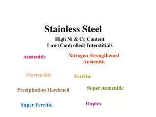
Features of a dressed RF cavity Niobium cavity under external pressure. Helium vessel sees internal pressure. Fermilab SRF helium vessels
Pressures • Helium around niobium cavity and within helium vessel • Vacuum within cavity and around helium vessel, so absolute pressure is differential pressure • 2 bar warm is lowest practical warm design pressure due to connection to a cryogenic system • Generally need higher cold allowable for loss-of-vacuum venting • Extremely high heat flux with loss of vacuum requires higher pressure for venting through a practical pipe size Fermilab SRF helium vessels
Safety/compliance issue • In the U.S., the Code of Federal Regulations allows national laboratories to follow national consensus pressure vessel rules or use of alternative rules which provide a level of safety greater than or equal to that afforded by ASME Boiler and Pressure Vessel Code. • Thus, while used for its superconducting properties, niobium ends up also being treated as a material for pressure vessels. Fermilab SRF helium vessels
Issues for code compliance • Cavity design that satisfies level of safety equivalent to that of a consensus pressure vessel code is affected by • use of the non-code material (niobium), • complex forming and joining processes, • a shape that is determined entirely by cavity RF performance, • a thickness driven by the cost and availability of niobium sheet, • and a possibly complex series of chemical and thermal treatments. Fermilab SRF helium vessels
Issues for code compliance - 2 • Difficulties emerge with ASME code Division 1 (which provides specific rules for pressure vessel details) in various areas • Material not approved by the ASME code • Loadings other than pressure • Thermal contraction • Tuning • Geometries not covered by rules • Weld configurations difficult to inspect Fermilab SRF helium vessels
Helium vessel materials • Cavity -- pure niobium • Purity is an issue • High RRR for thermal conductivity • No surface inclusions or flaws • Helium vessel • Presently titanium with NbTi transitions • Working toward stainless steel • Vessel includes a bellows for tuning Fermilab SRF helium vessels
Stainless Steel Vessel Status • The following summary of stainless steel vessel status was provided by Jeff Brandt Fermilab SRF helium vessels
Stainless Steel Vessel Status -- Analysis and Modeling • The initial 3-D modeling is complete. Some of those parts may change slightly based on testing and FEA now in process, but preliminary results show the design is strong enough and stiff enough. • The initial 3-D model and related 2-D axi-symmetric models are being used in both mechanical and thermal FEA by Serena Barbanotti, Bob Wands, and Sergei Cheban. • Thermal analysis of the newly configured niobium end joint is complete. This shows the simplification of combining the flange, the short tube piece, and a short elliptical portion of the end cell is thermally acceptable at full gradient. Fermilab SRF helium vessels
Stainless Steel Vessel Status -- Niobium Weld • An RF analysis of this weld joint by Ivan Gonin shows that the weld location will not limit or disturb the RF performance of the cavity. • Weld test of the end cell to newly configured niobium end flange is complete. Results show joint can be made in one pass from one side without re-melting nearby braze joint. Fermilab SRF helium vessels
Stainless Steel Vessel Status -- Braze Joint • 3-D modeling of test braze components is complete. Engineering drawings for these models are released. Procurement of (12) sets of parts is complete except for the braze foils, which were due 11-Sep-09. • Furnace brazing of those test components will commence upon receipt of braze foil. Three different braze alloys will be tested - 65Au/35Cu, 50Au/50Cu, and 100Cu. • Sectioning, Instron testing, and pressure testing of the braze joint are all planned. The alloy we are most happy with will be used to produce (2) brazed assemblies for the pressure test. All parts for a pressure test assembly are on hand. Fermilab SRF helium vessels
Stainless Steel Vessel Status -- Cavity Extension/Compression • Warm compression and stretching of cavities is routinely done as part of tuning. A 02-Sep-09 test has shown that AES-002 was able to be stretched warm 2.5 mm and still elastically return to its initial state. • We plan to stretch a cavity warm 1.5 mm after assembling the tuner. After cool-down with additional contraction of SS vessel, the cavity should be in its desired position. Fermilab SRF helium vessels
Conclusions • FEA in process is trying to prove we understand this system mechanically and thermally, and that the forces and stresses experienced are withing allowable limits. Piezo columns will potentially be more heavily loaded, and FEA is in process to understand this as well. • Engineering note is not officially started, yet much of the work required for it is already complete. • Plan for next year is to complete test brazing, complete FEA analysis, revise 3-D models and produce engineering drawings, procure SS vessel components, and produce a prototype SS dressed cavity for testing. Fermilab SRF helium vessels