Download
1 / 48
480 likes | 577 Views
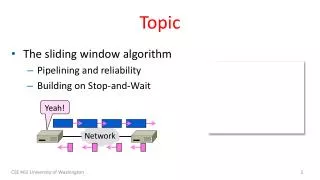
Learn about Proportional Control (PID), Encoder Application, and more. Experiment with LEGO wheel control using a shaft encoder. Understand overshoot and oscillations in control systems. Improve control response with proportional-derivative control.

E N D
Topic 29 • 29a PD Control Using an Encoder • 29b Flex Bend Sensors • 29c PID Control Using Flex Bend Sensors Vincent Crossley, Fall 2004
PD Control Using an Encoder Topic 29A Vincent Crossley, Fall 2004
Goals • Become familiarized with: • Proportional Control • Proportional Derivative Control • Application of PD control using an encoder
Proportional Control Proportional Control
Proportional Control Proportional Control Proportional control is the primary alternative to on-off or “bang-bang” control (see end of Lecture 29b “Flex Bend Sensors” for on-off example). If the difference between the current device output and its desired value (the current error) is large, the software should probably change the drive signal a lot. If the error is small, it should change it only a little. In other words, we always want a change like: P * (desired - current) where P is a constant proportional gain set by the system's designer. Unfortunately, proportional control alone is not sufficient in all control applications. One or more of the requirements for response time, overshoot, and oscillation may be impossible to fulfill at any proportional gain setting. Information from http://www.netrino.com/Publications/Glossary/PID.html
Proportional Control Proportional Control • Control algorithm generates a stronger response the farther away the system is from the goal state — response of control algorithm is proportional to amount of error • Test system: experiment with proportional control and proportional-derivative control • Control rotational position of LEGO wheel • Will vary power to motor, i.e., motor speed • Load shaft encoder driver: • load qencdr10.icb • Test shaft encoder: • encoder10_counts= 0; • while (1) { printf("%d\n", encoder10_counts); msleep(50L);} The proportional-derivative control test system includes a dc motor driving a two-stage gear reduction, and a large LEGO wheel which gives the system a fair bit of momentum (load on the system). At the middle stage of the gearing, a quadrature-based shaft encoder keeps track of the shaft position.
Proportional Control Proportional Control • Turn on motor, wait, turn it off, and then print out the encoder reading (6-hole pulley wheel gives 24 counts/revolution on encoder): • {encoder10_counts=0; motor(0, 100); msleep(100L); off(0); msleep(500L); printf("%d\n", encoder10_counts);} • Proportional Error Controller: Set the encoder counter to 0, and then write an infinite loop to repeatedly set the motor speed to the difference between a desired position and actual position: • {encoder10_counts= 0; while (1) {motor(0, 100 - encoder10_counts);}} • When the program starts to run, the difference between the desired position (setpoint =100) and the actual position (0) is 100, so the motor turns on full speed, driving the wheel toward the desired position. As it starts going, the error becomes progressively smaller. When it’s halfway, at position 50, the error is only 50, so at that point the motor goes at 50% of full power. When it arrives at the intended position of 100, the error is zero, and the motor is off. • Proportional Gain (ratio between error and power): Instead of a one-to-one ratio between error counts and motor power percentage, modify the controller so it multiplies the error value by 5: • {encoder10_counts= 0; while (1) {motor(0, 5 * (100 -encoder10_counts));}} • Response should feel much “snappier.” The wheel should reach the setpoint position faster, and it should resist being turned away from it much more aggressively.
Proportional Control Proportional Control • Overshoot: when the system goes beyond its setpoint and has to change direction before stabilizing on it. For the test system of a LEGO wheel turning in space, overshoot doesn’t seem to be much of a problem, but imagine if the system were a robot arm moving to a particular position. If it went beyond the position on its way getting there, it could have collided with some object just beyond the setpoint position. • Oscillations: are related to overshoot. After the system goes beyond its setpoint, when it corrects and drives the other way it can “overshoot” in the other direction as well. Then the phenomenon repeats and one sees the system going back and forth around the setpoint, in a nervous or jittery manner. • Serious concern to system designer: minimize both overshoot and oscillation, but provide adequate system response to changes in setpoints. void collect_data() { int i, power, counts; for (i= 0; i< SAMPLES;) { counts= encoder10_counts; power= pgain * (0 - counts); motor(0, power); data[i++]= counts; data[i++]= power; } } • pgain is proportional error gain, • units are conversion between error counts and percentage of full power, e.g., gain of 10 means 10-count error results in a full power action. • Power represents % full power calculated by control function • Position is actual encoder counts.
Pgain = 10 Pgain = 20 Proportional Control Proportional Control • Data taken every 0.2 seconds of real time. System is driven from 100 counts to 0 counts • Pgain=10: Full-power command as wheel heads toward setpoint. • When position within 10 counts of zero, power command began to fall off. • System overshot the zero point, and had to turn around • Offset Error: System did not stabilize at the goal. From around the 1.2 second mark onward, the position was fixed at a count of 1. This generated a power command of 10%, which was too small to activate the motor. • Pgain=20: should ameliorate the offset problem, since the same static error will result in a higher power command • Offset error is solved • Another problem: the beginnings of an oscillation. Now the system overshoots three times—twice beyond the setpoint and once before it.
Proportional Control Proportional Control • Pgain=30: Oscillation problem is more pronounced; there are a total of five oscillatory swings • Pgain=50: Oscillation behavior has taken over • System moves to within a slight distance from the setpoint, but cannot stabilize at the setpoint • Even a small error generates a power command that moves the system across the setpoint, resulting in a power command in the opposite direction • While the position error is small on the graph, the power command swings are quite evident. Pgain = 30 Pgain = 50
Proportional-Derivative Control Proportional-Derivative Control
Proportional-Derivative Control PROBLEM: The biggest problem with proportional control alone is that you want to reach new desired outputs quickly and avoid overshoot and minimize ripple once you get there. Responding quickly suggests a high proportional gain; minimizing overshoot and oscillation suggests a small proportional gain. Achieving both at the same time may not be possible in all systems. Information from http://www.netrino.com/Publications/Glossary/PID.html
Proportional-Derivative Control SOLUTION: Fortunately, we do generally have (or can derive) information about the rate of change of the system’s output. If the output is changing rapidly, overshoot or undershoot may lie ahead. In that case, we can reduce the size of the change suggested by the proportional controller. The rate of change of a signal is also known as its derivative. The derivative at the current time is simply the change in value from the previous sample to the current one. This implies that we should subtract a change of: D * (current - previous) where D is a constant derivative gain. The only other thing we need to do is to save the previous sample in memory. In practice, proportional-derivative (PD) controllers work well. The net effect is a slower response time with far less overshoot and ripple than a proportional controller alone. Information from http://www.netrino.com/Publications/Glossary/PID.html
Proportional-Derivative Control Proportional-Derivative Control void collect_data() { int i, power, counts, velocity; for (i= 0; i< SAMPLES;) { counts= encoder10_counts; velocity= encoder10_velocity; power= pgain * (0 - counts) - dgain * velocity; motor(0, power); data[i++]= counts; data[i++]= velocity; data[i++]= power; } } • Problem: Simply cranking up the pgain does not get the system to perform better • Motor drives output wheel to its position faster, but still overshoots/oscillates at higher gains • Driving at full power is appropriate when the system is far away from its setpoint • When pgain is high, then even a slight deviation from the setpoint causes a large power command • Solution: Correct for the momentum of the system as it moves toward the setpoint • Momentum is mass times velocity; therefore, momentum is directly proportional to velocity • Correct for the velocity when the system nears its setpoint by subtracting an amount from the power equation based on the velocity of the system Power command is now combination between proportion of error and velocity of system
Proportional-Derivative Control Proportional-Derivative Control pgain=4, dgain=1 • Pgain=4, Dgain=1: Overshoot is minimized, and there is no oscillatory behavior at all. • Pgain=10, Dgain=5: unstable; dgain is too large • Position graph: controller “puts on the brakes” too hard and the system stops moving before the destination setpoint (between the 0.8 and 1.0 second mark) • When the velocity hits zero, the proportional gain kicks in again and the system corrects • PD Control is used extensively in industrial process control • Combination of varying the power input when the system is far away from the setpoint, and correcting for the momentum of the system as it approaches the setpoint is quite effective pgain=10, dgain=5
Proportional-Derivative Control Proportional-Derivative Control • Discrete Sampling Error: Note discrete nature of the velocity graph, which is due to the fact that the encoder software calculates the velocity measure infrequently—every 0.15 seconds, as indicated by the steps in the velocity curve. (encoder driver takes difference between last encoder reading and current one to determine velocity) Since the testbed LEGO geartrain is overall a rather low-performance system, this is probably inconsequential, but this error is endemic to digital control systems and is a topic of much concern in control theory. • Classical control theory is all about analyzing the response of systems. By modeling mass of the system being controlled, power flow into the system, load on the system, and other characteristics, it is possible to determine optimal values for the gain factors. • Self-tuningor adaptive controllers: dynamically adjust gain parameters while system is in operation. This allows a controller to compensate for changing factors external to the system. Better than standard P-D controller. • PID control: “I” stands for integral; an integral term can correct for steady-state errors like in the first example, where the system came to rest a few counts away from the setpoint. By integrating this error over time, the controller can deliver a “kick” to drive the system to the setpoint. See “PID Control Using Flex Bend Sensors” Topic 29C.
Flex Bend Sensors Topic 29B Vincent Crossley, Fall 2004
Goals • Become familiarized with: • Flex bend sensors • Simple bang-bang control • Bang-bang control using flex bend sensor
What is a flex sensor? An analog sensor that changes resistance as it is flexed. As the plastic strip is bent (silver rectangles facing outward), the resistance increases. If rectangles face inward, resistance does not change from unflexed value.
Power Glove Was originally developed to detect finger flexing in Nintendo PowerGlove, and has since been used in other similar “glove” applications.
Specifications When unbent (flex of 0 degrees), nominal resistance is 10K Ohms. When flexed 90 Degrees, resistance is 30-40K Ohms.
Using The Sensor To use, connect to an analogue port, and flex readings will be between about 40 and 120. The readings are quite consistent so the sensor is appropriate for use where repeatability is needed.
Wall Following Useful for wall following:
Wall Following More wall following examples:
Simple Control The most simple way of control is a black-white, two state, or bang-bang control. This method is to just set the drive signal to its minimum value when you want the system to decrease its activity and to its maximum value when you want the system to increase its activity. This strategy is called on-off control, and it is how many thermostats work. Information from http://www.netrino.com/Publications/Glossary/PID.html
Simple Control On-off control doesn't work well in all systems. If the thermostat waits until the desired temperature is achieved to turn off the heater, the temperature may overshoot. See above diagram. The same amount of overshoot and ripple probably isn't acceptable in an elevator. Information from http://www.netrino.com/Publications/Glossary/PID.html
Simple Control This type of control can be implemented in the use of the flex bend sensor. The following is code for wall following assuming a left mounted sensor. int calibrate = analog(flex_sensor); // Allows user to set desired space between wall and robot while (1) { int space = analog(flex_sensor); // Reads current space if (space < calibrate) motor(left,50) // Going away from wall, tell robot to go left else motor(right,50) // Otherwise, it’s going towards wall, tell robot to go right msleep(100L); } Please refer to Topic 29C “PID Control Using Flex Bend Sensors” for more advanced controlling methods.
PID Control Using Flex Bend Sensors Topic 29C Vincent Crossley, Fall 2004
Goals • Become familiarized with: • PID control • PID control using flex bend sensor
PID Control Proportional Integral Derivative Control The basic idea is that the output of a PID controller should be a linear combination of the error, the integral of the error, and the derivative of the error.
PID Control Why is this better than PD in some cases? (PD Control is discussed in Lecture 29A, “PD Control Using an Encoder”) A problem is that PD control alone will not always settle exactly to the desired output. In fact, depending on the proportional gain, it's altogether possible that a PD controller will ultimately settle to an output value that is far from that desired. The problem occurs if each individual error remains below the threshold for action by the proportional term. (Say the error is 3, P = 1/8, and integer math is used.) The derivative term won't help anything unless the output is changing. Something else needs to drive the system toward the setpoint. That something is an integral term. Information from http://www.netrino.com/Publications/Glossary/PID.html
PID Control Proportional Integral Derivative Control P (Proportional): Allows system to recover from a change in reference value I (Integral): Eliminates Steady State Error Decreases settling time Increases Overshoot D (Derivative): Smoothes out the response Decreases Overshoot Increases settling time
PID Control Proportional Integral Derivative Control P: PD: PI: PID: T = throttle Ti = initial throttle K = constants (“gain”) E = error (actual – reference)
Theoretical and Actual Data Using Different Control Methods With Flex Bend Sensor The following slides show the application of P, PI, PD, and PID control using theoretical MatLab plots and also with the flex bend sensor. Please note that in the flex bend examples the gains could have been fine tuned to produce better results. These are just general examples to show the application of these controls.
P Control Theoretical P Control The above plot shows that the proportional controller reduced both the rise time and the steady-state error, increased the overshoot, and decreased the settling time by small amount. Information found at http://www.engin.umich.edu/group/ctm/PID/PID.html#characteristics
P Control Proportional Control Data Plots Using Flex Bend Sensor
P Control Proportional Control Code while(1) { float L; float R; while(analog(4)>calib)//if moving towards wall, go right { L=20.0+(5.0*(float)(analog(4)-calib)); //flex>calib, pos motor(0,(int)L); off(1); sleep(0.005); off(0); a++; data[a][0] = seconds(); data[a][1] = (float)analog(4); } motor(1,20); motor(0,20); while(analog(4)<calib)//if moving away from wall, go left { R=20.0-(5.0*(float)(analog(4)-calib)); //flex<calib, neg motor(1,(int)R); off(0); sleep(0.005); off(1); a++; data[a][0]= seconds(); data[a][1]=(float)analog(4); } } } //motor 0 is left motor //motor 1 is right motor persistent float data[300][2]; // Optional, for data recording void main() { int calib; int a = -1; // for data recording printf("Set Desired Space and Press Start \n"); while(!start_button()) { calib=analog(4); } printf("Calib=%d\n",calib); reset_system_time();
PD Control Theoretical PD Control This plot shows that the derivative controller reduced both the overshoot and the settling time, and had small effect on the rise time and the steady-state error. Information found at http://www.engin.umich.edu/group/ctm/PID/PID.html#characteristics
PD Control Proportional Derivative Control Data Plots Using Flex Bend
PD Control Proportional Derivative Control Code motor(1,20); motor(0,20); while(analog(4)<calib)//if moving away from wall, go left { int j=0; int jj=1; int derivative_R_error; while(j<=3) { int R_error = analog(4)-calib; R_array[j] = R_error; if( jj = 4 {jj = 0;} if(jjj != 1) { derivative_R_error = R_array[jj]-R_array[j]; if(derivative_R_error > 0){derivative_R_error = 0;} } R=30.0-(2.0*(float)(analog(4)-calib))+(2.0*(float)(derivative_R_error)); // flex<calib, neg motor(1,(int)R); off(0); sleep(0.005); off(1); j++; jj++; } jjj++; } } int calib; while(1) { float L; float R; int sum_L_error; int sum_R_error; int L_array[] = {0,0,0,0}; int R_array[] = {0,0,0,0}; int iii=1; int jjj=1; while(analog(4)>calib)//if moving towards wall, go right { int i=0; int ii=1; int derivative_L_error; while(i<=3)// jump out of loop when all four arrays filled { int L_error = analog(4)-calib;// error L_array[i] = L_error; if( ii = 4)// reset leading array to zero when last one is filled {ii = 0;} if(iii != 1)// skips over first time through loop, since need two arrays filled to get correct data { derivative_L_error = L_array[ii]-L_array[i];// error of leading array minus one before it if(derivative_L_error < 0){derivative_L_error = 0;}//only necessary if moving away from wall } L=30.0+(2.0*(float)(analog(4)-calib))-(2.0*(float)(derivative_L_error)); // P - D motor(0,(int)L); off(1); sleep(0.005); off(0); i++; ii++; } iii++; }
PI Control Theoretical PI Control We have reduced the proportional gain (Kp) because the integral controller also reduces the rise time and increases the overshoot as the proportional controller does (double effect). The above response shows that the integral controller eliminated the steady-state error. Information found at http://www.engin.umich.edu/group/ctm/PID/PID.html#characteristics
PI Control Proportional Integral Control Data Using Flex Bend
PI Control Proportional Integral Control Code int calib; while(1) { float L; float R; int sum_L_error; int sum_R_error; int L_array[] = {0,0,0,0}; int R_array[] = {0,0,0,0}; while(analog(4)>calib)//if moving towards wall, go right { int i=0; while(i<=3) { int L_error = analog(4)-calib; L_array[i] = L_error; sum_L_error = L_array[0] + L_array[1] + L_array[2] + L_array[3]; L=30.0+(2.0*(float)(analog(4)-calib))+(0.4*(float)(sum_L_error)); //P + I, flex>calib, pos motor(0,(int)L); off(1); sleep(0.005); off(0); i++; } } motor(1,20); motor(0,20); while(analog(4)<calib)//if moving away from wall, go left { int j=0; while(j<=3) { int R_error = analog(4)-calib; R_array[j] = R_error; sum_R_error = R_array[0] + R_array[1] + R_array[2] + R_array[3]; R=30.0-(2.0*(float)(analog(4)-calib))-(0.4*(float)(sum_R_error)); //flex<calib, neg motor(1,(int)R); off(0); sleep(0.005); off(1); j++; } } }
PID Control Theoretical PID Control Now, we have obtained the system with no overshoot, fast rise time, and no steady-state error. Information found at http://www.engin.umich.edu/group/ctm/PID/PID.html#characteristics
PID Control Proportional Integral Derivative Control
PID Control Proportional Integral Derivative Control motor(1,20); motor(0,20); while(analog(4)<calib)//if moving away from wall, go left { int j=0; int jj=1; int derivative_R_error; while(j<=3) { int R_error = analog(4)-calib; R_array[j] = R_error; sum_R_error = R_array[0] + R_array[1] + R_array[2] + R_array[3]; if( jj = 4) {jj = 0;} if(jjj != 1) { derivative_R_error = R_array[jj]-R_array[j]; if(derivative_R_error > 0){derivative_R_error = 0;} } R=20.0-(5.0*(float)(analog(4)-calib))-(0.5*(float)(sum_R_error)) +(5.0*(float)(derivative_R_error)); //P-I+D motor(1,(int)R); off(0); sleep(0.01); off(1); j++; jj++; } jjj++; } } int calib; while(1) { float L; float R; int sum_L_error; int sum_R_error; int L_array[] = {0,0,0,0}; int R_array[] = {0,0,0,0}; int iii=1; int jjj=1; while(analog(4)>calib)//if moving towards wall, go right { int i=0; int ii=1; int derivative_L_error; while(i<=3)// jump out of loop when all four arrays filled { int L_error = analog(4)-calib;// error L_array[i] = L_error; sum_L_error = L_array[0] + L_array[1] + L_array[2] + L_array[3]; if( ii = 4)// reset leading array to zero when last one is filled {ii = 0;} if(iii != 1)// skips over first time through loop, since need two arrays filled to get correct data { derivative_L_error = L_array[ii]-L_array[i];// error of leading array minus one before it if(derivative_L_error < 0){derivative_L_error = 0;}//only necessary if moving away from wall } L=20.0+(5.0*(float)(analog(4)-calib))+(0.5*(float)(sum_L_error)) -(5.0*(float)(derivative_L_error)); //P+I-D motor(0,(int)L); off(1); sleep(0.01); off(0); i++; ii++; } iii++; }
Tuning There are ways to make these controllers more accurate. The “K” constants (gains) can be found by trial and error, but they can also be found more accurately using equations. (i.e. Zeigler-Nichols Tuning) To learn more take the ME Controls course!
Conclusion As you can see using PID control can greatly increase accuracy. This can be very useful for tasks like wall following, line following, or driving in a straight line. Choosing which type of control to use is dependent on what type of system it is being applied to. Sometimes all that is needed is P control, while other times PID control is necessary.