Download
1 / 56
580 likes | 1k Views
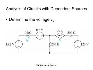
Circuits with Dependent Sources. Chapter 3. Circuit with Dependent Sources. V 1 = 60 volts because the 20 Ω resistor is in parallel; by Ohm’s law, V 1 = I 2 ·20 Ω ; so I 2 = V 1 /20 Ω = 60v/20 Ω = 3 A. Circuit with Dependent Sources.

E N D
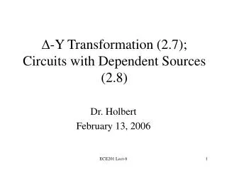
Circuits with Dependent Sources Chapter 3
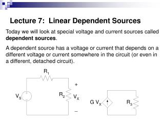
Circuit with Dependent Sources V1 = 60 volts because the 20Ω resistor is in parallel; by Ohm’s law, V1 = I2·20Ω; so I2 = V1/20Ω = 60v/20Ω = 3 A
Circuit with Dependent Sources If I2 = 3 A, then the 5Ω·I2 dependent source is 15 volts and if V1= 60 v., then the V1/4Ω dependent source is 15 A
Circuit with Dependent Sources Writing Kirchoff’s Voltage law around the outside loop, -60 v + 5Ω·I2 + 5Ω·I3 = 0 where I2=3 A, so I3 = (60–15)v / 5Ω = 9 A
Circuit with Dependent Sources Writing Kirchoff’s Current law at B I4 + I3 + V1/4 = 0 (all leaving node B) Since V1/4Ω =15 A and I3 = 9 A, I4 = -24 A
Circuit with Dependent Sources Writing Kirchoff’s Current law at A I4 + I1 – I2 = 0 Since I2 = 3 A and I4 = -24 A, I1 = 27 A
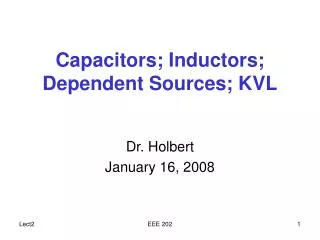
Circuit with Dependent Sources I4= -24A 60 v source generating, P=-27A·60v=-1620 watts 5·I2 source absorbing, P=24A·15v=360 watts V1/4 source absorbing, P=15A·45v= 675watts I1=27A V2= 45v I1/4Ω=15A
Circuit with Dependent Sources 20 Ω resistor absorbing, P=3A·60v=180 watts 5 Ω resistor absorbing, P=9A·45v= 405 watts -1620 w +360 w + 675 w + 180 w + 405 w = 0 I3=9A V1=60v I2=3A V2=45v
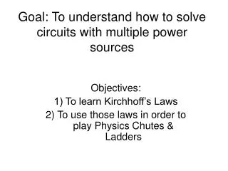
VA = 28 volts Find I1 2 Amps by Ohm’s law (I2∙14=28) Find I2 2 Amps by KCL (4-I1-I2=0) Find VB 24 volts by KVL (-I1∙14+I2∙2+VB=0) Find I3 6 Amps by Ohm’s law (I3∙4=24) Find I4 4 Amps by KCL (I2+I4-I3=0)
Sources in Series + - V1 Voltage sources In series add algebraically + - V1+V2 + - V2
Sources in Series + - V1 Start at the top terminal and add. If hit a + (+V1) If you hit a – (-V2) + - V1-V2 - + V2
Sources in Series + - 8·Vx If one source is dependent, then so is the equivalent + - 8·Vx-V2 - + V2
Sources in Series Is Current sources in series must be the same value and direction Is Is
Sources in Parallel Current sources in parallel add algebraically I1 I2 I1+I2
Sources in Parallel Current sources in parallel add algebraically I1 I2 -I1+I2
Sources in Parallel If any source is dependent, then the combination is also dependent I1 5·Ix -I1+5·Ix
Sources in Parallel Voltage sources in parallel must be the same value and same direction + - + - + - Vs Vs Vs
Source Transformation Section 5.2
Source Transformation • Practical voltage sources are current limited and we can model them by adding a resistor in series • We want to create an equivalent using a current source and parallel resistance for any RL Practical Source RS + VL - IL + - Vs RL
Source Transformation • VL and IL must be the same in both circuits for any RL Practical Source + VL - IL Ip Rp RL
Source Transformation • VL and IL must be the same in both circuits for RL= 0, or a short circuit • Ip = IL and VL = 0 Practical Source + VL - IL Ip RL=0 Rp
Source Transformation • Now look at the voltage source in series with the resistor with a short circuit • IL= Vs/Rs and VL = 0 • So Ip = Vs/Rs Practical Source RS + VL - IL + - Vs RL=0
Source Transformation • VL and IL must also be the same in both circuits for RL= ∞, or an open circuit • IL = 0 and VL = Ip·Rp Practical Source + VL - IL Ip RL=∞ Rp
Source Transformation • Now look at the voltage source in series with the resistor with an open circuit • IL= 0 and VL = Vs, so Vs = Ip·Rp • If Ip = Vs/Rs, then Rp = Rs Practical Source RS + VL - IL + - Vs RL=∞
Example • We can transform the voltage source • Why? Gets all components in parallel 10Ω + Vo - I1 4A + - 20v 15Ω 6Ω
Example • We can combine sources and resistors • Ieq = 2A+4A = 6A, Req = 3Ω + Vo - 20v/10Ω =2A 4A 10Ω 15Ω 6Ω
Example • Vo = 6A· 3Ω = 18 v + Vo - 6A 3Ω
Example • Going back to the original circuit, Vo=18 v • KCL: I1+ 4A - 1.2A - 3A=0, so I1=0.2A 10Ω + Vo = 18 v - 4A I1 18/15 =1.2A 18/6 =3A + - 20v 15Ω 6Ω
Example • We can transform the current source after first combining parallel resistances • Why? Gets all components in series 10Ω + Vo - 4A + - 20v 15Ω 6Ω
Example • We can transform the current source after first combining parallel resistances • Req=6·15/(6+15)=30/7 Ω 10Ω + Vo - 4A + - 20v 30/7Ω
Example • We can now add the series voltage sources and resistances • Rtotal=100/7 Ω and Vtotal=20/7 volts 10Ω 30/7Ω I1 + - + - 20v 120/7v
Example • We can easily solve using KVL for I1 • I1 = 20/7 ÷ 100/7 = 0.2 A 100/7 Ω I1 + - 20/7 v
Voltage & Current Division Chapter 3, Section 8
Voltage Division • We could have a circuit with multiple resistors in series where we want to be able to find the voltage across any resistor • Clearly Req = Σ Ri, and I = Vs/Req • So Vi = I·Ri = Vs ·(Ri/Req) . . . . . . R1 Ri + Vi - I + - Vs Rn
Voltage Division Application • You have a 12 volt source, but some devices in your circuit need voltages of 3 and 9 volts to run properly • You can design a voltage divider circuit to produce the necessary voltages . . . . . . R1 Ri + Vi - I + - Vs Rn
Voltage Division Application • To get 3, 6 and 3 across the three resistors, any R, 2·R and R could be used • 9 volts is available at A, 3 volts at B R 2·R B A + 3v - + 6v - + 3v - + 9v - + - R 12 v
Wheatstone Bridge • This circuit is often used to measure resistance or convert resistance into a voltage. 300Ω 100Ω + 100v - B + VAB - A 500Ω R
Wheatstone Bridge • Using the voltage divider at A, • VAD = 100 v ∙ R/(100+R)Ω 300Ω 100Ω + 100v - B + VAB - A 500Ω R D
Wheatstone Bridge • Find the Voltage at B, using the voltage divider theorem 300Ω 100Ω + 100v - B + VAB - A 500Ω R
Wheatstone Bridge • VBD = 100 v ∙ 500Ω/(300+500)Ω = 62.5 v 300Ω 100Ω + 100v - B + VAB - A 500Ω R D
Wheatstone Bridge • Let’s find the relationship between VAB & R • VAB = VAD – VBD = 100∙R/(100+R) – 62.5 300Ω 100Ω + 100v - B + VAB - A 500Ω R D
Wheatstone Bridge • The Wheatstone bridge is considered balanced when VAB=0 v. • Find R • R=167Ω 300Ω 100Ω + 100v - B + VAB - A 500Ω R
Current Division • What if we want to find the current through any parallel resistor? • Req = 1 / Σ(1/Ri) and V = Is·Req • So Ii = V / Ri = Is·(Req/Ri) . . . . . . + V - Is Ii R1 Ri Rn
Wheatstone Bridge • The 10 A current source divides between the two branches of the bridge circuit 300Ω 100Ω I2 10 A I1 + VAB - 500Ω 100Ω D
Wheatstone Bridge • First, simplify by combining the series resistances in each branch of the bridge 300Ω 100Ω I2 10 A I1 + VAB - 500Ω 100Ω D
Wheatstone Bridge • First, simplify by combining the series resistances in each branch of the bridge I1 I2 10 A 100+100Ω 300+500Ω
Wheatstone Bridge • Find the parallel equivalent resistance • Req = 200∙800/(200+800) Ω = 160 Ω I1 I2 10 A 100+100Ω 300+500Ω
Wheatstone Bridge • I1 = 10 A ∙(160/200) = 8 A • I2 = 10 A ∙(160/800) = 2 A I1 I2 10 A 100+100Ω 300+500Ω
Voltage Division Vi = Vs · Ri/Req Req = Σ Ri Ri/Req < 1 Vi < Vs Series resistors only Current Division Ii = Is · Req/Ri Req = 1÷ Σ (1/Ri) Req/Ri < 1 Ii < Is Parallel resistors only Voltage vs Current Division