Download

1 / 31

E N D
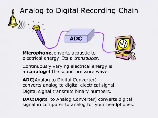
Digital Audio • PCM • It is the standard form of digital audio in computers, Compact Discs, digital telephony and other digital audio applications. In a PCM stream, the amplitude of the analog signal is sampled regularly at uniform intervals, and each sample is quantized to the nearest value within a range of digital steps. • PCM streams have two basic properties that determine their fidelity to the original analog signal: the sampling rate, the number of times per second that samples are taken; and the bit depth, which determines the number of possible digital values that each sample can take.
PDM • In a PDM signal, specific amplitude values are not encoded into pulses of different size as they would be in PCM. • Pulse-width modulation (PWM) is the special case of PDM where all the pulses corresponding to one sample are contiguous in the digital signal. • A PDM bitstream is encoded from an analog signal through the process of delta-sigma modulation. • The process of decoding a PDM signal into an analog one is simple: one only has to pass the PDM signal through a low-pass filter. This works because the function of a low-pass filter is essentially to average the signal.
PPM • Pulse-position modulation (PPM) is a form of signal modulation in which M message bits are encoded by transmitting a single pulse in one of 2^M possible time-shifts.
CS43L22 Audio-DAC • Discovey kit has on-board Audio-DAC with integrated amplifier, the Cirrus Logic CS43L22 • CS43L22 has two ports: one port for the digital audio signal, and one port for control signals. • Both of these ports are serial interfaces, the audio portion a fairly standard I2S interface, the control port a standard I2C interface.
What is I2S? • Optimized for digital audio data transmission • 3-line serial bus lines • SD: Two time-multiplexed data channels • WS: Word Select (0=left channel, 1 = right channel) • SCK: Clock • Bus master generates SCK and WS • Bus master = transmitter or separate controller • SCK synchronizes transmitter and receiver • Serial data format • Two’s complement, MSB sent first • If system word > #transmitted bits, truncate after LSB • If system word < #transmitted bits, add 0’s after LSB
Looking at the schematic for the STM32F4-Discovery, the I2S lines connect to pins of the SPI3 peripheral, and the I2C lines to pins of the I2C1 peripheral. Therefore both of these peripherals need to be configured. • First everything should be set up on the STM32F4 side, then CS43L22 also needs a bit of initializing via the control port.
Step1: Clocks • The GPIO peripherals that we need to configure are GPIOA (I2S_WS signal), GPIOB (I2C_SDA & I2S_SCL), GPIOC (I2S_MCK, I2S_SCK, I2S_SD) and GPIOD (Reset pin on CS43L22). • RCC_AHB1PeriphClockCmd(RCC_AHB1Periph_GPIOA | RCC_AHB1Periph_GPIOB | RCC_AHB1Periph_GPIOC | RCC_AHB1Periph_GPIOD, ENABLE) • the two serial peripherals that we need (SPI3, I2C1- they share the same system bus:APB1). • RCC_APB1PeriphClockCmd(RCC_APB1Periph_I2C1 | RCC_APB1Periph_SPI3, ENABLE); • the I2S peripherals have their own PLL module to provide accurate standard audio sampling frequencies. • RCC_PLLI2SCmd(ENABLE);
Step3: I2S • we will need to #include “stm32f4xx_spi.h I2S_Cmd(SPI3, ENABLE);
Step4: I2C We will need to #include “stm32f4xx_i2c.h” GPIO_SetBits(GPIOD, GPIO_Pin_4);
void send_codec_ctrl(uint8_t controlBytes[], uint8_t numBytes) { uint8_t bytesSent=0; while (I2C_GetFlagStatus(CODEC_I2C, I2C_FLAG_BUSY)) {/*just wait until no longer busy*/} I2C_GenerateSTART(CODEC_I2C, ENABLE); while (!I2C_GetFlagStatus(CODEC_I2C, I2C_FLAG_SB)) {/*wait for generation of start condition*/} I2C_Send7bitAddress(CODEC_I2C, CODEC_I2C_ADDRESS, I2C_Direction_Transmitter); while (!I2C_CheckEvent(CODEC_I2C, I2C_EVENT_MASTER_TRANSMITTER_MODE_SELECTED)) {/*wait for end of address transmission*/} while (bytesSent < numBytes) { I2C_SendData(CODEC_I2C, controlBytes[bytesSent]); bytesSent++; while (!I2C_CheckEvent(CODEC_I2C, I2C_EVENT_MASTER_BYTE_TRANSMITTING)) {/*wait for transmission of byte*/} } while(!I2C_GetFlagStatus(CODEC_I2C, I2C_FLAG_BTF)) {/*wait until it's finished sending before creating STOP*/} I2C_GenerateSTOP(CODEC_I2C, ENABLE); } I2C Send
uint8_t read_codec_register(uint8_t mapbyte) { uint8_t receivedByte = 0; while (I2C_GetFlagStatus(CODEC_I2C, I2C_FLAG_BUSY)) {/*just wait until no longer busy*/} I2C_GenerateSTART(CODEC_I2C, ENABLE); while (!I2C_GetFlagStatus(CODEC_I2C, I2C_FLAG_SB)) {/*wait for generation of start condition*/} I2C_Send7bitAddress(CODEC_I2C, CODEC_I2C_ADDRESS, I2C_Direction_Transmitter); while (!I2C_CheckEvent(CODEC_I2C, I2C_EVENT_MASTER_TRANSMITTER_MODE_SELECTED)) {/*wait for end of address transmission*/} I2C_SendData(CODEC_I2C, mapbyte); //sets the transmitter address while (!I2C_CheckEvent(CODEC_I2C, I2C_EVENT_MASTER_BYTE_TRANSMITTING)) {/*wait for transmission of byte*/r} I2C_GenerateSTOP(CODEC_I2C, ENABLE); while (I2C_GetFlagStatus(CODEC_I2C, I2C_FLAG_BUSY)) {/*just wait until no longer busy*/} I2C Receive
I2C_AcknowledgeConfig(CODEC_I2C, DISABLE); I2C_GenerateSTART(CODEC_I2C, ENABLE); while (!I2C_GetFlagStatus(CODEC_I2C, I2C_FLAG_SB)) { //wait for generation of start condition } I2C_Send7bitAddress(CODEC_I2C, CODEC_I2C_ADDRESS, I2C_Direction_Receiver); while (!I2C_CheckEvent(CODEC_I2C, I2C_EVENT_MASTER_RECEIVER_MODE_SELECTED)) { //wait for end of address transmission } while (!I2C_CheckEvent(CODEC_I2C, I2C_EVENT_MASTER_BYTE_RECEIVED)) { //wait until byte arrived } receivedByte = I2C_ReceiveData(CODEC_I2C); I2C_GenerateSTOP(CODEC_I2C, ENABLE); return receivedByte; }
MP45DT02 MEMS Microphone • The MP45DT02 MEMS microphone outputs a PDM signal, which is a high frequency (1 to 3.25 MHz) stream of 1-bit digital sample • The output is acquired in blocks of N samples by using a synchronous serial port (SPI or I2S) of the STM32 microcontroller. The microphone's PDM output is synchronous with its input clock; therefore an STM32 SPI/ I2S peripheral generates a clock signal for the microphone.