Download
1 / 167
1.96k likes | 2.29k Views
DESIGN OF REINFORCED CONCRETE STRUCTURES. B.Tech III YEAR I SEM ( CE502PC ) Prepared By : Mr. MOHD MUBASHEER SHAHZEB. Ass istant Professor Department of Civil Engineering. 1. UNIT-I DESIGN CONCEPTS. 2. W ORKING S TRESS D ESIGN.

E N D
DESIGN OF REINFORCED CONCRETE STRUCTURES B.TechIII YEAR ISEM (CE502PC) PreparedBy: Mr. MOHD MUBASHEER SHAHZEB AssistantProfessor Department of CivilEngineering 1
UNIT-I DESIGNCONCEPTS 2
WORKING STRESSDESIGN • The sections of the members of the structure are designed assuming straight line stress-strain relationships ensuring that at service loads the stresses in the steel and concrete do not exceed the allowable workingstresses. • The allowable stresses are taken as fixed proportions of the ultimate or yield strength of thematerials. • The B.Ms and forces that act on statically indeterminate structures are calculated assuming linear – elastic behaviour. 3
ULTIMATE STRENGTHDESIGN • Sections of members of the structures are designed taking inelastic strains into account to reach ultimate (maximum) strength when an ultimate load, equal to the sum ofeach service load multiplied by its respective load factor, is applied to the structure. • The beginning moments and forces that act as statically indeterminate structures at the ultimate load are calculated assuming non linear elastic behaviour of the structure up to the ultimate load. i.e., redistribution of same actions are taking place due to nonlinear relationship betweenactions 4 anddeformations.
REASON FOR ULTIMATE STRENGTHDESIGN • Ultimate strength design allows a more rational selection of the loadfactors. • The stress-strain curve for concrete nonlinear and is timedependent. • Ultimate strength utilizes reserves of strength resulting from a more efficient distribution of stresses allowed by inelastic strains, and at times the working stress method is veryconservative. 5
WHAT IS LIMITSTATE? • “A limit state is a state of impending failure, beyond which a structure ceases to perform its intended function satisfactorily, in terms of either safety or serviceability”. 6
DE SIGNCONCEPTS • ►Safety: implies that the likelihood of (partial or total) collapse of structure is acceptably low not only under (normal loads) service loads but also underoverloads. • ►Serviceability: satisfactory performance of structure under service loads without discomfort to user due to excessive deflections, cracking, vibrationetc. • Other con7siderations such as durability, impermeability, acoustic • and thermal insulationetc.
LIMIT STATEDESIGN • Limit States • Purpose: to achieve acceptable probability that a structure will not become unfit for its intended use i.e. that it will not reach a limit state. • Thus, a structure ceases to be fit for use will constitute a limit state and the design aims to avoid any such condition being reached during the expected life of thestructure. • Two principle types of limit stateare; • Ultimate LimitState • Serviceability LimitState
SERVICEABILITY LIMITSTATES • Other limit statesinclude • Excessive vibration: which may cause discomfort or alarm as well as damage. • Fatigue: must be considered if cyclic loading islikely. • Fireresistance:thismustbeconsideredintermsofresistanceto • collapse, flame penetration and heattransfer. • Special circumstances: any special requirements of the structure which are not covered by any of the more common limit states, such as earthquake resistance, must be taken intoaccount.
ASSUMPTIONS FOR DESIGN INFLEXURE At any cross-section, sections which are plane prior to bending remain plane after bending. Or strain varies linearly with distance from neutral axis i.e. plane sections remain plane inbending. The maximum strain in concrete at the outermost fiber is0.0035. Stress-strain relationship in concrete could be either rectangular, parabolic or combination of rectangular and parabolic curves which should be agreeable with the experimentalresults.
PARTIAL FACTORS OF SAFETY FORLOADS • Errors and inaccuracies may be due to a number ofcauses: • Design assumptions and inaccuracy ofcalculation. • Possible unusual loadincreases. • Unforeseen stressredistributions. • Constructionalinaccuracies • These are taken into account by applying a particular factor of safety (γf) on the loadings, sothat • Design load =characteristicload x partial factor of safety(γf) • This factor should also take into account the importance of the limit state under consideration and reflect to some extent the accuracy with which different type of loading can be predicted, and the probabili1t1y of particular load combinationsoccurring.
WHAT IS DESIGNSTRENGTH? • In design calculations “Design Strength” for a given material and limit state is obtained by dividing the characteristic strength by the partial safety factor for strength, appropriate to that material and that limitstate. • When assessing the strength of a structure or structural member for the limit state of collapse, the partial safety factor should be taken as 1.5 for concrete and 1.15 for steel
PARTIAL FACTORS OF SAFETYFOR MATERIALS(ΓM) • The strength of material in an actual member will differ from that measured in a carefully prepared test specimen and it is particularly true for concrete where placing, compaction and curing are so important to the strength. Steel, on the other hand, is a relatively consistent material requiring a small partial factor ofsafety. • The severity of the limit state being considered. Thus, higher values are taken for the ultimate limit state than for the serviceability limitstate.
CHARACTERISTICSTRENGTH • “Characteristic strength is defined as the strength of material below which not more than 5 percent of the test results are expected tofall”. • Strength of concrete varies for the same concrete mix, which give different compressive strength in laboratorytests. • Variability in strength evidently depends on degree of quality control. • Variability in strength is measured in terms of either the “Standard Deviation” or the Coefficient of Variation (COV), which is the ratio of standard deviation to mean strength(fcm).14
NORMAL PROBABILITYCURVE • Strength of materialsuponwhichdesign is based on that strength is assumed to benormal. • Characteristic value is defined as that value below which it is • unlikely that more than 5% of the results willfall. • fckfm1.64 = CharacteristicStrength = Standard Deviation fck fm fckand • The relationshipbetween accounts for variationsin fm resultsof testspecimens and withthe method, and control of manufacture, quality of construction and type ofmaterials 15
CHARACTERISTICLOADS • Loads on structures can also be assessedstastically. • Characteristic Load = Mean Load ± 1.64 (standarddeviation). • In most cases, it is the maximum loading on a structural member that is critical and the upper, positive value given by the above expression. • Butthelower,minimumvaluemayapplywhenconsideringthe • stability of the behaviour of continuousmembers.
COMPRESSION FAILURE OF SINGLY REINFORCED BEAM • To assessthetrue behavior of section,stress-straincurve for concrete should beassumed. • Strain is proportional to distance from neutralaxis. • Shape of stress-strain curve indicates shape of compressive stress block at various stages ofloading.
STRESS-STRAIN DISTRIBUTION IN COMPRESSED CONCRETE • When total compressive force in concrete multiplied by lever arm is maximum, section of beam reduces maximum moment of resistance. • In case, cross-sectional area of steel reinforcement bars is large as HYSD bars areused. • Compressive strength of concrete will be exhausted prior to steel bars start yielding. Depth of neutral axis increasesconsiderably. • Compressive force increases and crushing will takeplace • Crushing failure issudden,which isan explosive nature and occurs withoutwarning. 18
TENSION FAILURE OF SINGLY REINFORCED BEAMS • Incase,cross-sectionalarea ofsteelreinforcementissmall atsome value of load; steel bars will attain their yieldpoint. • Tensileforceinsteelbarsremainsconstant at0.87Astfy increasingloading. even with • A small additional load causes large plastic elongation of steel. Atthat • stress, steel bars yield and stretch to a largeamount. • Tensioncracksarewidened;whichpropagate simultaneous significant deflections ofbeam. upwards withthe • Atthisstagestressdistributioninconcretebecomesnon-linear.The • mean stress in concrete increases. In order to maintain equilibrium between internal forces, then depth of neutral axisreduces. 19
BALANCED BEAMSECTION • Beam section is called “Balanced Section” in case, area of steel reinforcement in the section is such that the maximum compressive strain in bending in concrete attains “εcu” simultaneously as the strain in steel reaches,εsy1. • A singly reinforced rectangular beam section of breadth, b and effective depth, d. • As per limit state of collapse, εcu = 0.0035. Therefore, a balanced section, is defined for design purposes as one in which the steel stress reaches the design strength simultaneously as the concrete reaches the strain 0.0035. 20
UNDER REINFORCED BEAMSECTION • A beam section is called “Under Reinforced” in case the area of steel reinforcement provided in the beam section is such that the steel ratio is less than that for balanced section,pb. • As bending moment increases, the strain in steel εs reaches its limiting value, εsy , while strain in concrete, εc remains still below its ultimate value (0.0035). • In an under reinforced beam, steel yields prior to crushing of concrete in compression. Since, crushing of concrete does not occur, (collapse of beam does not occur), until strain in concrete at extreme fibre in compression attains,εcu. • Beam sectioncontinuestoresistincreasingappliedmomentandthe • neutral axis shiftsupwards. • Leverarmincreasessomewhatwhilethetotal concrete remainsunaltered. compressiveforc2e1 in
OVER-REINFORCED BEAMSECTION • A beam section is called over-reinforced if the area of steel reinforcement in the beam sections is such that the ratio of steel, p is more than that for of the balanced section,pb. • Strain in concrete in compression reaches the ultimate strain, εcu = 0.0035 prior to strain in steelreaches • In over-reinforced beam failure initiates in theconcrete. • In crushing failure of concrete, deflection of beam remains small and there is no extensivecracking. • Sudden failure withoutwarning. 22
DESIGN OF SINGLY REINFORCEDBEAMS • Following are the usual steps in the design of singly reinforcedbeams. • Step-1. The effective span is needed to determine maximum moment and maximum shearforce. • For simply supportedspans. • Effective span = clear span + effectivedepth • ls = centre to centre ofsupports. • widthofsupportsattwoendsofbeamsmaybeassumedas300 • mm or600mm. • for Cantilever beam • Effective span = clear projection+ • Step-2.Loadsactingonthebeamaregiven. The max. momentand 23 max. shear forces should be calculated. calculated. Then, factored loads are
SIDE FACEREINFORCEMENT • When the overall depth of beam becomes more than 750mm, side face reinforcement shall be provided along the two faces of the beam section, to take into consideration the crack width limitation and lateral buckling of the web inbeam. • Side face reinforcement shall not be less than 0.1 percent of web area and shall be distributed equally in two faces at a spacing not exceeding 300mm or web thickness whichever isless. 24
SPACING OFREINFORCEMENT • In order to ensure proper placement of concrete around the main reinforcement bars and to achieve full surface contact between the bars and concrete, it is necessary to maintain a certain minimum distance between adjacentbars • Clear horizontal distance between two adjacent parallel reinforcing bars shall not be less than maximum of thefollowing • diameter of the bar (for equaldiameter) • diameter of larger bar (unequalbars) • 5 mm more than the nominal maximum size of coarseaggregate. • Clear vertical distance shall not be lessthan main a. 15mm two-thirds of max-size ofaggregate maximum diameter of mainbar. 25
d EFFECTIVESPAN • Effective span of a member is computed asfollows:- • Simplysupportedbeamorslab:effectivespanofasimplysupporte • member is taken as lesser of thefollowing:- • l = Lc +d • l= l (l = centre to centre distance betweensupports) • Where Lc = clearspan • d = effective depth of beam orslab 26
EFFECTIVESPAN • Continuous beam or slab; effective span of a continuous beam or slab is calculated as follows:- • If the width of support is less than or equal to Lc/12, the effective span is taken as lesser of thefollowing:- • i. l = Lc +d, • ii. Centre to centre distance betweensupports. • If width of support is greater than Lc/12 or 600mm, whichever is less, the effective span is taken asfollows:- • i. For end span with one end fixed and the other continuous or forintermediate span; i. l =Lc ii. For end span with one end free and the other continuous: the effective spanis the lesserof i. l = Lc +0.5d ii. l = Lc +0.5ts ts = is the width of the discontinuoussupport 27
GUIDELINES FOR DESIGN OFBEAMS • The depth of the beam should satisfy the deflection requirements w.r.t L/d ratios. In addition, for economy, the ratio of overall depth to width should be between 1.5 and 2.0. • In T-beams the depth of slab is usually taken as about 20 percent of the overall depth of thebeam. • For main bars, choose one size if possible. In any case, limit the main bars to two sizes and that too without much variation in diameter between thetwo. • Usualwidthsofbeamsadoptedinmmare;150,200,230,250,275and • 300mm. • Beam width should be equal to or less than the dimension of thecolumn 28 in to which itframes.
WORKING STRESSDESIGN • The sections ofthemembers ofthe structureare • designed assuming straight line stress-strain relationships ensuring that at service loads the stresses in the steel and concrete do not exceed the allowable working stresses. • The allowable stresses are taken as fixed proportions of the ultimate or yield strength of thematerials. • The B.Ms and forces that act on statically indeterminate structuresarecalculatedassuminglinear–elastic • 29 • behaviour.
ULTIMATE STRENGTHDESIGN • Sections of members of the structures are designed taking inelastic strains into account to reach ultimate (maximum) strength when an ultimate load, equal to the sum ofeach service load multiplied by its respective load factor, is applied to the structure. • The beginning moments and forces that act as statically indeterminate structures at the ultimate load are calculated assuming non linear elastic behaviour of the structure up to the ultimate load. i.e., redistribution of same actions are taking place due to nonlinear relationship betweenactions 30 anddeformations.
REASON FOR ULTIMATE STRENGTHDESIGN • Ultimate strength design allows a more rational selection of the loadfactors. • The stress-strain curve for concrete nonlinear and is timedependent. • Ultimate strength utilizes reserves of strength resulting from a more efficient distribution of stresses allowed by inelastic strains, and at times the working stress method is veryconservative. 31
DESIGN OF FLANGEDBEAMS • In reinforced concrete construction, slab is supported overbeams. • Simpleconcreteslabsofmoderatedepthandweightarelimitedtospans • of 3m to5m • If it is desired for long spans without excessive weight and material, slab is built monolithically with RC beams and beams are considered as flangedbeams. • At the interior portions of floor, slab with beam acts as a T-beam and at an end the portion acts as anL-beam. • Shear reinforcement of beams and bent bars extend into slab and • Completeconstructioniscastintegrally.Apartofslabactswithupper 32 part in bending compressivestresses.
EFFECTIVE WIDTH OFFLANGE • Theoretically width of flange is supposed to act as top flange of beam. • Elements of flange midway between webs of two adjacent beams are less highly stressed in longitudinal compression than those elements directly over webs ofbeams. • An effective width of flange, bf is used in the design of flanged beam and is treated to be uniformly stressed at the maximum value, which is smaller than actual width offlange. • Effectivewidthofflangeprimarilydependsonspanofthebeam, breadth of web, bw and thickness of flange,Df. 33
LOCATION OF NEUTRALAXIS • Depending upon proportions of cross-section, reinforcement in tension, strength ofmaterials area of steel • Neutral axis of a T-beam in one case may lie in the flange i.e. depth of NA, xu is less than or equal to thickness of flange or depth of slab, Df (Neutral axis lies within flange (xu <Df)) • NAmaylieinwebi.e.depthofneutralaxis,xuismorethan • thickness of slab, Df. • Stress diagram consists of a rectangular portion of depth 0.43xu and a parabolic portion of depth0.57xu. 34
(2) NEUTRAL AXIS LIES OUT SIDE FLANGE [I.E. XU >DF] • When NA of T-section lies outside flange, it lies in web of T-beam. However, there are two possibilities depending upon whether depth of flange Df is less than or equal to 0.43xu or Df is more than 0.43xu. • Comparison of Df with 0.43xu (i.e. 3/7xu) is more rational as 0.43xu is actual depth of rectangular portion of stressblock. • In IS:456-2000, if (Df/d) is less than 0.2, the flange of T-beam is considered as small. • Dfis less than0.43xu • Total area in compression consists of sum of compressive force in concrete in web of width, bw,Cw, cuand compressive forc3e5in concrete in the flange excluding web,Cf,cu.
(2) NEUTRAL AXIS LIES OUT SIDE FLANGE [I.E. XU >DF] i. Df > 0.43 xu or (Df >0.2d) i. Depth of flange Df is more than 0.43xu, some portion is subjected to uniform stress equal to 0.446fck (0.43xu) and remaining portion is subjected to parabolicstress. i.To obtain compressive force inportion of flange, concept of modified thickness of flange equalto yf = (0.15xu +0.65Df) is recommended byIS456-2000. i. Average stress is assumed to be0.446fck
CLASSIFICATION OFTORSION • PrimaryTorsion-requiredtomaintainbasicstatic • equilibrium • SecondaryTorsion-required tomaintain only • compatibilityof joiningmembers. • Torsionencounteredinstatically members-PrimaryTorsion. determinate • Torsioninstaticallyindeterminate SecondaryTorsion. members-
TORSIONAL STIFFNESS OFHOMOGENEOUS • SECTIONS • To analyze a statically indeterminate structure it is necessaryto • determine the relative stiffness of variousmembers. • The transfer of torsional moment depends up on the torsion stiffness “KT” of a member, defined as the torsional moment “T” required to produce unit angle oftwist • For circular shaft, diameter, D, torsion is givenby • T G J r l
TORSIONALSTIFFNESS TGJ TGJ • Torsional stiffness= = T K l l • J = Torsionconstant E 2(1) • G = shear modulus= • T =Torsion • =angleof twist over length‘l’ • l =lengthof the member over which occurs • = Poisson’s ratio = 0.15 forconcrete • When cross section is circular, the torsion constantis D4 J 32 39
TORSION OF NONCIRCULARMEMBERS • Crosssectionappearstoremainsameincircularshapes even afterapplicationof torsionsincetheshaperemains • circular even aftertwisting. • This is not true in non-circular crosssections. • Maximum shearing stress does not occur at the corners of rectangular section, but at themiddleof longerside. 40
TORSIONCONSTANT • In RCconstruction,crosssectionisgenerallyrectangular with width “b” and depth, D[D>b]. • Torsion constant for rectangular section is J = β b3D (D>b), where β is afunctionof theratioof D-to-b i.e.(D/b) • Amoreconvenientexpressionfor“J”,forvaluesof D/b < 10, has been derived byTimoshenko bb3D J10.63D 3 • When b/D <1/10 b3D J 3 41
EFFECT OF TORSIONREINFORCEMENT • A plain concrete beam fails practically as soon as diagonal crackingoccurs. • A beamsuitablyreinforcedcansustainincreasedtorsion moment until eventually failure occurs byyieldingof steel. • Cracks develop on three faces with crushing on thefourth. • Torsionreinforcementconsistsofacombinationof longitudinal barsand links orstirrups. • Longitudinalbarsshouldbedistributedevenlyroundthe insideperimeterof link.
INTERACTION OF TORSION AND BENDING • Torsion occurs simultaneously withflexure. • Many studies reported on the interactionbetween bending andtorsion. • There has been no agreement on correct interaction criterion. • Both theSkew Bending Theoryand the Space Truss Analogydeveloped by Lampert are in general agreement on the interactionbehavior.
AccordingtoCollinsandLampert,underpositive bending,yieldingof bottom reinforcementoccurs: • when equal volumes of longitudinal and transverse steel are used,and • when equalamountsof longitudinal steel are used in the top and bottomfaces.
For members with symmetrical reinforcement, the interactionof • torsion and bending moment is representedby 22 T M u u 1 1 T M uouo A fsc Force in Steel inCompression sc 1 A f Force in Steel inTension s st Where Tu= Ultimate torsion in the presence offlexure Tuo= Torsional strength when the member is subjected to torsionalone Mu= Ultimate flexural moment in the presence oftorsion Muo= Flexural strength when the member is subjected to flexurealone
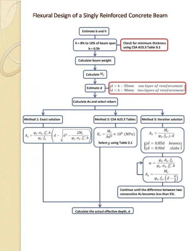
DOUBLY REINFORCEDBEAMS When beam depth is restricted and the moment the beam has to carry is greater than the moment capacity of the beam in concrete failure. When B.M at the section can change sign. When compression steel can substantially improve the ductility of beams and its use is therefore advisable in members when larger amount of tension steel becomes necessary for itsstrength. Compression steel is always used in structures in earthquake regions to increase theirductility. Compression reinforcement will also aid significantly inreducing the long-term deflections ofbeams. 46
DESIGNSTEPS Determine the limiting moment of resistance Mum for the given cross-section using the equation for a singly reinforcedbeam Mu,lim = 0.87fy.Ast,1 [d - 0.42xu,m] = 0.36 fck.b.xu.m [d - 0.42xu,m] If the factored moment Mu exceeds Mlim, a doubly reinforced section is required (Mu - Mlim) =Mu2 Additional area of tension steel Ast2 is obtained by considering the equilibrium of force of compression in comp. steel and force of tension T2 in the additional tensionsteel σsc Asc – σcc Asc = 0.87fy Ast2 σsc Asc = 0.87 fyAst2 Asc = compressionsteel. 47 σcc = Comp. stress in conc at the level of comp. steel =0.446fck.
ANALYSIS OF DOUBLY REINFORCEDSECTIONS Effect of Compression Reinforcement on the Strength and Behavior Less concrete is neededto resist the T and thereby moving the neutral axis (NA)up. T Asfy C T
ANALYSIS OF DOUBLY REINFORCED SECTIONS Effect of Compression Reinforcement on the Strength and Behavior Singly Reinforced a CCc ; Mn Asf d 1 y 2 Doubly Reinforced a C CcCs ; Mn Asf and a2a1 d 2 y 2
EFFECT OF COMPRESSION REINFORCEMENT Section2: T Asfs T CsCc1 Section1: T A f s s TCc10.85fcba0.85fcb1c1 Asfs0.85fcba Asfs 2 c Asfs0.85fcb1c2 1 0.85 fcb1 Af Asfs c s s 2 0.85fb c 1 Addition of A’s strengthens compression zone so that less concrete is needed to resist a given valueofT. NA goes up (c2 <c1) and s increases (s2>s1).