Download
1 / 36
360 likes | 461 Views
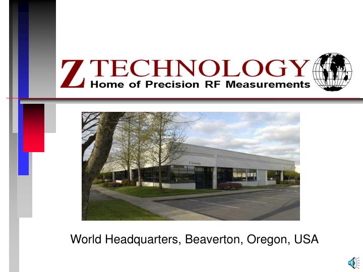
World Headquarters, Beaverton, Oregon, USA. Our business. Design and Manufacture of RF coverage measurement and mapping instrumentation Emphasis on digital and analog television coverage measurement Specific expertise in automated RF measurement and analysis of DTV quality of service.

E N D
Our business • Design and Manufacture of RF coverage measurement and mapping instrumentation • Emphasis on digital and analog television coverage measurement • Specific expertise in automated RF measurement and analysis of DTV quality of service
Our television customers • Transitioning to 8VSB digital service • Operating analog and digital plants • New transmission formats • New power levels • New channel assignments • New antenna locations • New government regulations • Cost and people constrained
Antenna Patterns • Not always as you would expect 6.5 miles from 1000’ AAT Horizontal Gain Vertical Angle Gain Oded Bendov / Krishna Praba, Television Engineering Handbook, Jerry Whitaker
Z Technology measurement systems • Address specific measurement needs • documentation • identification • acceptance • confirmation • resolution
DSS5800 DTV measurement system Programmable field strength meter 8VSB data demodulator GPS Receiver Power and Distribution Laptop Windowstm PC AC DC
DSS5800 DTV measurement system Programmable field strength meter 8VSB data demodulator GPS Receiver Power and Distribution Laptop Windowstm PC AC DC
DSS5800 DTV measurement system Programmable field strength meter 8VSB data demodulator GPS Receiver Power and Distribution Laptop Windowstm PC AC DC
DSS5800 DTV measurement system Programmable field strength meter 8VSB data demodulator GPS Receiver Power and Distribution Laptop Windowstm PC AC DC
Three measurement techniques 1. Drive testing • rapid accumulation of data • identification of problem coverage areas 2. Calibrated testing • used to validate more general data • communicates very specific values 3. On-site testing • detailed evaluation of local conditions
Drive Testing • Rapid accumulation of coverage data • Calibrated measurement equipment • 7 ft. antenna height, on roads • Automatic capture and recording • Identification of problem areas • Relative to previous runs • Poor signal coverage • Changes in coverage
Drive Test Considerations • Equipment configuration • Antenna, Power, Mounting, Calibration • Convenience and Safety • Environment • Location, Obstructions, Reflections • Operator interface • Driver Distraction, Information Displays • Setup & Automatic Collection of Data
Mobile Test Antennas • Horizontal dipole • General direction towards transmitter • Magnet mount, ~24” above roof surface • Calibrated; antenna factors for dBuV/m • Vertical sampling antenna • Mag mount 1/4 wave vertical antenna • Not true to horizontal component • Characterized
Mobile Test Antennas • Omnidirectional antennas • Generally lower gain, uncalibrated • Subject to multipath distortions • Rotators • Dipoles are broad pattern • Just need a general direction • Beware of distracting driver
Antenna Correction Factors • Measured correction factors supplied by antenna manufacturer • Add antenna factor plus cable loss to receiver reading in dBuV to convert to field intensity in dBuV/Meter. • Example: • Antenna Correction Factor 16.0 dB/m • Cable loss .9 dB • Meter Reading 44.0 dBuV • Field Intensity 60.9 dBuV/meter
Calibrate Antenna Setup • Mount antenna and adjust element length for frequency as indicated in manufacturer’s table • Connect to measurement equipment with calibrated cable • Add antenna correction factor for operating frequency and calibrated losses • Enter system correction factor into meter or PC application software • Meter or application will read field intensity in dBuV/m
Multiple Frequency Testing • Same band, one antenna • Factory antenna factors • Element length vs. frequency vs. factor • Characterizing for multiple frequencies • Multiple Antennas • Power combiners • Filters • System characterization
VHF UHF LP Filter Power Combiner dBuV/m HP Filter VHF ant correction factor - cable loss - LPF loss - Combiner loss - cable loss = VHF Antenna Factor (sys) UHF ant correction factor - cable loss - HPF loss - Combiner loss - cable loss = UHF Antenna Factor (sys) Add antenna factor plus cable loss to receiver reading in dBuV to convert to field intensity in dBuV/Meter. Multiple Antennas
Calibration Procedures • Equipment certification • NIST traceable antennas, cables, field strength meter • Secondary reference • Equipment setup • 30 ft. antenna height vs. vehicle rooftop • Antenna factors recorded with data
Drive Test Procedure • Set up job • Frequencies • Antenna factors • Signal types • Adjust antenna direction • Spectrum display • Sample measurement • Start Drive Test • Hit record • Drive the route
Signal Level (voltage) At Cursor Position (frequency) 8.8 dB 0.33 MHz (freq) Percent Reflection (Voltage) At Cursor position (Delay) 20 Log(.38)=8.4 dB Main Tap normalized To 100% 3 uS (time) 38% of Main Tap Energy (voltage) Example Case: One major reflection at 3 uS causes a .33 Mhz ripple on the Spectrum Display
Operational Precautions • Do not operate while driving • Be aware of antenna orientation • Stop and enter comments where appropriate • Analyze recorded data later
The Drive Test • Set up the “job” for signal types and frequencies • Click F1 “Sample” to check the reception • Click F3 “Record Continuous” • Drive until direction changes more than ~30 degrees; stop and adjust antenna direction • Click F4 “Stop Measurements” • Take a break and look at the data
Automatic data recording • Analog: records all setups, time, location, direction of travel, peak power, antenna factors, frequencies, etc. • Digital: adds wideband parameters; integrated power, etc. • DTV systems add data from the digital decoder; sync/eq locks, tap values, etc. • Clear text data files are easy to read and export to other applications
Analyzing the data • Real-time map plotting • Colored trail of dots for any parameter • Plots value as a color for each GPS location measured • Color may be automatically or manually scaled
Analyzing the data • Map oriented data • Colored trail of dots for any parameter • Tool-tip displays selected value for selected location • Right-click for all data taken at that location
On-Site Testing • Problem resolution • Difficult locations • Sniff out problems • Using customer antennas • Site suitability
RF signal measurement products • Systems designed to meet specific industry needs • digital and analog RF field strength measurements • automatic signal coverage mapping • 8VSB/DVB-T demodulated data analysis
Our mission • Address the RF measurement needs of our customers • Provide economical, real-time assistance and solutions • Increase the confidence level of the technical operator • Enable the gathering of historical data for reference as conditions change
Learn more about our systems Z Technology, Inc. 1815 NW 169th Place, Suite 3070 Beaverton, Oregon 97006 USA Tel: 503.614.9800 Fax: 503.614.9898 www.ztechnology.com sales@ztechnology.com Factory Contacts: Guy Lewis, John Purdy, Jim Zook