Download
1 / 37
370 likes | 596 Views
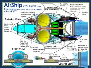
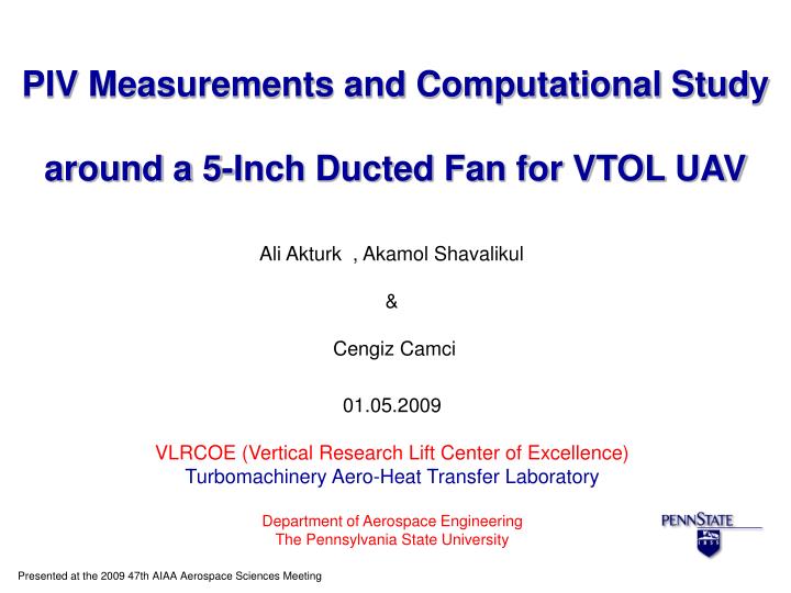
PIV Measurements and Computational Study around a 5-Inch Ducted Fan for VTOL UAV. Ali Akturk , Akamol Shavalikul & Cengiz Camci. 01.05.2009 VLRCOE (Vertical Research Lift Center of Excellence) Turbomachinery Aero-Heat Transfer Laboratory Department of Aerospace Engineering

E N D
PIV Measurements and Computational Study around a 5-Inch Ducted Fan for VTOL UAV Ali Akturk , Akamol Shavalikul & Cengiz Camci 01.05.2009 VLRCOE (Vertical Research Lift Center of Excellence) Turbomachinery Aero-Heat Transfer Laboratory Department of Aerospace Engineering The Pennsylvania State University Presented at the 2009 47th AIAA Aerospace Sciences Meeting
Overview • INTRODUCTION • OBJECTIVES • DUCTED FAN MODEL • EXPERIMENTAL SETUP • PARTICLE IMAGE VELOCIMETER (PIV) • EXPERIMENTAL RESULTS AND DISCUSSION • THE SPECIFIC ACTUATOR DISK BASED FAN MODEL • SUMMARY AND CONCLUSIONS Turbomachinery Aero-Heat Transfer Laboratory
Introduction DUCTED FAN VTOL VEHICLES Turbomachinery Aero-Heat Transfer Laboratory
Introduction • There has been many studies to quantify the flow field properties around ducted fans. • Martin and Tung tested a ducted fan in hover condition and in forward flight with different crosswind velocities. They have measured aerodynamic loads and performed hot-wire velocity surveys at inner and outer surface of the duct and across the downstream wake. • Fleming, Jones and Lusardi conduct wind tunnel experiments and computational studies on 12” ducted fan. They have concentrated on ducted fan performance in forward flight. Turbomachinery Aero-Heat Transfer Laboratory
Introduction • Graf, Fleming and Wings improved ducted fan forward flight performance with new design leading edge geometry which has been determined to be the significant factor in offsetting the effects of the adverse aerodynamic characteristics. • Lind, Nathman and Gilchrist carried out a computational study using panel method. Turbomachinery Aero-Heat Transfer Laboratory
Introduction • He and Xin developed the ducted fan models based on a nonuniform and unsteady ring vortex formulation for duct and lade element model for fan. • Zhao and Bil proposed CFD simulation to design and analyze an aerodynamic model of a ducted fan UAV in preliminary design phase with different speeds and angles of attack. Turbomachinery Aero-Heat Transfer Laboratory
Objectives • The main aim is to analyze complicated flow field around the ducted fan in hover and horizontal flight conditions is investigated . • A ducted fan that has a 5” diameter is used for analysis. • Quantification of velocity field at the inlet and exit of the ducted fan by Planar PIV measurements. • To generate an efficient definition of fan boundary condition using for actuator disk model. Turbomachinery Aero-Heat Transfer Laboratory
Ducted Fan Model Turbomachinery Aero-Heat Transfer Laboratory
Experimental Setup Cross Wind Blower NOT TO SCALE Turbomachinery Aero-Heat Transfer Laboratory
PIV Camera Fan Blades Laser Beam Source PIV Camera Calibration plate Particle Image Velocimeter (PIV) • Basic steps of PIV experimental procedure : • Flow is seeded. • The flow region of interest is illuminated. • Scattering light from the particles forming the speckle images is recorded by cameras. • Recordings are analyzed by means of correlation software. Turbomachinery Aero-Heat Transfer Laboratory
Fan Blades Particle Image Velocimeter (PIV) • In our experiments: • 80C60 HiSense PIV/PLIF camera • Nikon Micro-Nikkor 60/2.8 objective • Double cavity frequency doubled pulsating Nd:YAG laser • Seeding particles has diameter of 0.25-60 m. Laser Sheet CCD Camera Laser Head Turbomachinery Aero-Heat Transfer Laboratory
PIV Camera Fan Blades Particle Image Velocimeter (PIV) • Procedure used in our system : • Aligning camera and laser sheet. • The image pairs of PIV domains are recorded. • The image maps are divided into 32 x 32 pixel interrogation areas and 25% overlapping is used which generated 1748 vectors. • All the image pairs are adaptive correlated, moving average validated and then ensemble averaged to obtain true mean flow. • Measurement domains size : [156 mm x 96 mm] Turbomachinery Aero-Heat Transfer Laboratory
PIV Camera Particle Image Velocimeter (PIV) • The ensemble size is of critical importance in achieving statistically stable mean velocity distributions in SPIV data reduction process. Turbomachinery Aero-Heat Transfer Laboratory
PIV Camera Fan Blades Particle Image Velocimeter (PIV) Ensemble size of 400 is optimal in achieving a statistically stable average in the current set of experiments. Turbomachinery Aero-Heat Transfer Laboratory
Fan Blades Experimental Results AXIAL VELOCITY CONTOURS 9000 Rpm & 15000 Rpm @ Hover Condition Turbomachinery Aero-Heat Transfer Laboratory
Fan Blades Experimental Results 9000 Rpm 9000 Rpm 15000 Rpm Turbomachinery Aero-Heat Transfer Laboratory
Fan Blades Experimental Results RADIAL VELOCITY CONTOURS 9000 Rpm & 15000 Rpm @ Forward Flight LEADING SIDE TRAILING SIDE Turbomachinery Aero-Heat Transfer Laboratory
Experimental Results 6.05m/s 9000 Rpm LEADING SIDE LEADING SIDE TRAILING SIDE TRAILING SIDE 9000 Rpm 15000 Rpm Turbomachinery Aero-Heat Transfer Laboratory
Fan Blades Experimental Results VELOCITY MAGNITUDE CONTOURS & STREAMLINES 9000 Rpm @ Hover and Forward Flight Turbomachinery Aero-Heat Transfer Laboratory
Fan Blades Experimental Results 6.05m/s 9000 Rpm LEADING SIDE TRAILING SIDE Hover Forward Flight Turbomachinery Aero-Heat Transfer Laboratory
Fan Blades Experimental Results Duct Boundary 9000 Rpm Drop in axial velocity due to lip separation Turbomachinery Aero-Heat Transfer Laboratory
Fan Blades Experimental Results VELOCITY MAGNITUDE CONTOURS & STREAMLINES 15000 Rpm @ Hover and Forward Flight Turbomachinery Aero-Heat Transfer Laboratory
Experimental Results 6.05m/s LEADING SIDE TRAILING SIDE Turbomachinery Aero-Heat Transfer Laboratory
PIV Camera Fan Blades Specific actuator disk based fan model • Incompressible Navier Stokes equations are solved. • Unstructured computational mesh. • 700000 tetrahedral cells. • Symmetry boundary condition is applied at the side surfaces. • Pressure inlet and outlet boundary conditions are applied at top and bottom. • Pressure jump boundary condition is applied at the fan surface. PRESSURE INLET (atmospheric static pressure specified) Fan Surface PRESSURE OUTLET (atmospheric static pressure specified) Turbomachinery Aero-Heat Transfer Laboratory
PIV Camera Specific actuator disk based fan model Turbomachinery Aero-Heat Transfer Laboratory
PIV Camera Specific actuator disk based fan model Turbomachinery Aero-Heat Transfer Laboratory
Specific actuator disk based fan model Measured and computed axial velocity component @ the inlet of the ducted fan for 9000Rpm Hover condition Turbomachinery Aero-Heat Transfer Laboratory
Summary • Experimental and computational investigation around 5 inch diameter ducted fan for V/STOL UAV. • Planar PIV system used to measure velocity field aroundthe ducted fan. • Axial and radial velocity components at the inlet/exit region of the ducted fan were measured in hover and horizontal flight at 6m/s. • Computational study based on solving incompressible Navier-Stokes equations was carried out. • The specific actuator disk based fan-model used for pressure jump across the fan rotor. Turbomachinery Aero-Heat Transfer Laboratory
Conclusions • The performance of the ducted fan was highly affected from the crosswind velocity. • That separation bubble has proven to affect the exit flow of the fan rotor. • Non-uniformities introduced to the inlet and exit flow by the effect of crosswind. Turbomachinery Aero-Heat Transfer Laboratory
Conclusions • Increase in rotational speed enhances the performance at 9000 Rpm and15000 Rpm in hover condition. • Increase of rotational speed reduced effect of separation bubble. • The specific actuator disk based fan model was able to predict inlet flow velocity distribution well at 9000 Rpm. Turbomachinery Aero-Heat Transfer Laboratory
Computational Results r>0 r<0 Phase Locked Approached of PIV Measurements (Image recorded with digital camera on full laser power) Turbomachinery Aero-Heat Transfer Laboratory
PIV to Pitot Probe Comparison “Vertical” test arrangement Turbomachinery Aero-Heat Transfer Laboratory
PIV Validation with Pitot probe results Comparison between PIV and Pitot probe results W/o cylinder w/ cylinder
Ensemble effect (2) Definition: W/o cylinder w/ cylinder
Figure 24: Comparison of velocity profiles Out-of –plane component in-plane component axial (z-direction)