Download
1 / 30
350 likes | 508 Views
Cell Phones. ECE5367 Project Dr.Chen Fall 2004 Luong Tang Daisuke Hagiwara Shehzaad Bidiwala. S. Cell Phone Milestones. 1843 - Michael Faraday began research involving electrical conductivity through open space. His discoveries made cellular phones possible.

E N D
Cell Phones ECE5367 Project Dr.Chen Fall 2004 Luong Tang Daisuke Hagiwara Shehzaad Bidiwala S
Cell Phone Milestones • 1843 - Michael Faraday began research involving electrical conductivity through open space. His discoveries made cellular phones possible. • 1865 - Dr. Mahlon Loomis, a dentist, developed a method of wireless communication using kites. • 1973 - Dr. Martin Cooper, former general man-ager for systems division of Motorola, invented the portable handset and was the first to use it. Also set up the first base station in New York with the first working prototype. S
Cell Phone Milestones (cont’d.) • 1977 – Cellular phones are released to the public for testing purposes. First to Chi-cago, then to Washington D.C. and the Baltimore area. • 1979 – Cellular phones are tested in Japan. • 1988 – CTIA (Cellular Technology Industry Association) was developed to set stan-dards for the cellular phone providers. S
Cellular System • Typical cell-phone carrier gets about 800 frequencies to use across the city. • A city is divided into hundreds of cells (10 square miles) • Cells are normally thought of as hexagons on a big hexagonal grid • Each call uses two frequencies for duplex communcation, therefore there are about 400 voice channels • Each cell only use 56 voice channels, 1/7th of the available 400 channels L http://www.mat.ucsb.edu/~g.legrady/academic/courses/03w200a/projects/wireless/cell_technology.htm
Advantages of Cells • Cell phones have low-power transmitters in them. (0.6 watts and 3 watts) • The base station in each cell is also transmitting at low power. • Low-power transmitters have two advantages: • The transmissions of a base station and the phones are kept within a cell. Therefore, in the figure above, both of the purple cells can reuse the same 56 frequencies without interference. • Low power consumption of the cell phone. Meaning smaller batteries L http://www.mat.ucsb.edu/~g.legrady/academic/courses/03w200a/projects/wireless/cell_technology.htm
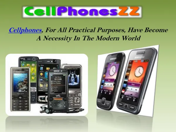
Components • Circuit board containing the brains of the phone • An antenna • A liquid crystal display (LCD) • A keyboard • A microphone • A speaker • A battery H http://www.mat.ucsb.edu/~g.legrady/academic/courses/03w200a/projects/wireless/cell_technology.htm
The circuit board • analog-to-digital: outgoing audio signals • digital-to-analog: incoming audio signals • digital signal processor (DSP): signal-manipulation calculations at high speed. • Microprocessor: controls the keyboard, display, commands and signals of the base station, and the rest of the board • ROM & Flash memory: storage for the phone’s operating system and customizable features • Radio frequency and power section: power management and recharging • RF amplifiers: works with signals to and from the antenna http://www.mat.ucsb.edu/~g.legrady/academic/courses/03w200a/projects/wireless/cell_technology.htm H
Inside a typical cell phone Microprocessor Flash memory H http://www.mat.ucsb.edu/~g.legrady/academic/courses/03w200a/projects/wireless/cell_technology.htm
The Nokia 3210 • Baseband architecture: HD947 • NSE–8/9 Series L
DC/DC converter • The battery voltage is 1.8V to 3.6V • depending on thebattery charge amount. • converted to one of 4voltage levels • in the range from 3.1 V to 4.2 V for RF L
CCONT • Multi functional power management IC • Provides Baseband power distribution • Uses voltage regulators • Feeds the power to the whole system. L
Cobba_GJP • Mixed signal RF and Audio codec • Provides A/D and D/A conversion • Audio signals • Two serial busses Data transmission with MAD2PR1 • Input/output signal sourceselection and gain control • Audio tones aregenerated and encoded by the MAD2PR1 and transmitted to theCOBBA_GJP for decoding S
UI Switch • Integrated switch IC for UI (User interface) purposes • control switches for • buzzer • vibra • LED– (display & keyboard) control S
MAD2PR1 • Takes care of all signal processing • Consists of MCU, system logic and DSP • All integrated into one commonASIC. H
MAD2PR1: The Digital Part • ARM RISC processor (16&32 bit instruction) • TMS320C542 DSP core • BusController • System Logic • UIF(Keyboard interface, serial control interface for COBBA_GJP PCM Codec, LCD Driver, and CCONT) • AccIF(Accessory Interface) • SCU(Synthesizer Control Unit) • SIMI(SimCard interface) • PUP(Parallel IO, USART) • FLEXPOOL(DAS00308 FlexPool Specification) • SERRFI(DAS00348 COBBA_GJP Specifications) H
RISC processor • Reduced Instruction Set Computer • computer arithmetic-logic unit that uses a minimal instruction set, emphasizing the instructions used most often and optimizing them for the fastest possible execution • faster instruction execution, such as engineering and graphics workstations and parallel-processing systems H
DSP • TMS320C542 DSP • 1 program memory bus, 3 data memory buses • 2 reads and 1 write operation can be performed in 1 cycle (25ns) • 40 MIPS (40 MHz) • 40-Bit Arithmetic Logic Unit (ALU) • Instructions With a 32-Bit Long Word Operand • Arithmetic Instructions With Parallel Store and Parallel Load H
Part of the DSP- TMS320C542 H http://focus.ti.com/lit/ds/symlink/tms320c542.pdf
PSCC • Battery Charging Control ASIC • controlled low drop power switch • input transient voltage protection • thermal self protection • output over voltage protection (voltage limit for phone hardware) • start–up regulator with limited charge current, Istart • provision for soft switching • control of different charger types H
Memory • FLASH Rom • EEPROM • SRAM H
SRAM (Shrink TSOP32) • The MCU work memory • size 128kB • Volatile: memory contents are lost when the Baseband voltage isswitched off • Memory bus share with Flash memory • 17 address lines, • 8 data lines S H
EEPROM (IIC SO8) • Contains all user changeable data • Tuningparameters and phone setup information. • short code memory forstoring user defined information • Size 16Kbytes H
FLASH Memory (uBGA48) • The MCU program codes • The programmemory size is 16 Mbits (1024kx16bit) • 20 address lines • 16 data lines H
Memory H
Summary: Memory • FLASH Rom: stores MCU program code, 2 MB, parallel memory bus 10 address lines and 16 data lines • EEPROM: stores system and tuning parameters user settings and selections, etc., nonvolatile, serial IIC bus, 16 kB, • SRAM: MCU work memory, parallel bus, 17 address lines and 8 data lines, 128 kB H
Cell Phone Statistics • In 1994, 16 million Americans subscribed to cellular phone services. • In 2001, the number grew to 110 million. • It is predicted to reach 1.2 billion by 2005. S
¿Questions? Thank you. S