Download
1 / 9
100 likes | 270 Views
Landing Gear Strut. Estimated time required : 15 min Experience level: Higher. MD Patran 2005 r2. What You Will Learn…. Importing Parasolid geometry files to MSC Patran and perform a FEA on such part Creating a finite element mesh on Parasolid geometry

E N D
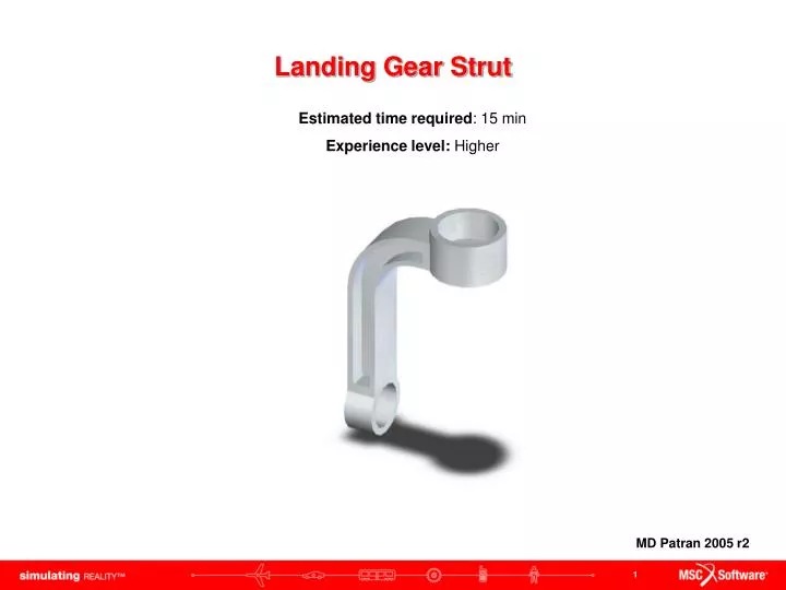
Landing Gear Strut Estimated time required: 15 min Experience level: Higher MD Patran 2005 r2
What You Will Learn… • Importing Parasolid geometry files to MSC Patran and perform a FEA on such part • Creating a finite element mesh on Parasolid geometry • Changing the viewport background color from black to white
Problem Description A part geometry of a front landing gear strut of an F-18 has been already created in a standard CAD software and exported into Parasolid geometry file format. This geometry file can now be imported into MSC Patran to conduct a FEA analysis. We would like to obtain the location of maximum and minimum stress as well as maximum deformation. With this information calculate the factor of safety (FS) for this strut. • Landing gear strut is made of steel • Modulus of Elasticity = 30 x106 psi • Poisson’s ratio = 0.3 • Yield strength = 36 ksi • A total load of 7080 lb is applied downward on the upper face of the strut • Constrain the hub cylinder at the bottom of the strut in all translational directions • Use Tetmesher with Tet10 topology
Importing Parasolid Geometry file from CAD a • After creating a new database file follow these instructions (for the database select the tolerance to be default) : • Click on File menu and select Import… • In Object pull down menu select Model • In Source pull down menu select Parasolid xmt • Select the file strut.xmt from the window (you might have to locate the file at the location were you saved it) • Click Apply button • You will hear a beep followed by a pop-up screen with the loaded geometry information summary. • Click Ok button b d c e f Note: It is important to know what kind of units the Parasolid geometry was created in. This is because when importing the geometry into Patran, the values for the dimension are imported too. Thus, the Loads/BC’s and element properties need to be of a consist unit base. g
Changing the Viewport Settings a b c • Click on Smooth shaded rendering icon • Click on Exchange Black/White icon • Click on ISO 1 View icon • The resulting viewport should look like this It would be a good idea to become familiar at this point with the viewport rotation, zooming and displaying standard views for the part.
Meshing Parasolid Part a • Click on Elements icon • Select Create / Mesh / Solid from the drop down menus • Under Elm shape select Tet • Under Mesher select TetMesh • Under Topology select Tet10 • In the Input List text field select the entire solid • Click on Automatic Calculation check box to turn it Off • In the Value text field enter 0.01 • Click Apply button b c d e f g h i
Suggestion of Steps that Proceed • Create Loads and Boundary conditions • Create material properties • Applying properties • Analysis • Results
Best Practices • When importing a geometry model with Parasolid, make sure you know what unit system was used to create such model. So that you know what kind of properties and loads have to be applied. • When importing geometries from CAD it is often the case that the model will have more geometrical features than needed to perform an accurate analysis. It is essential to be able to identify such excess features such as chamfers and fillets/rounds and suppress them before importing them to Patran. This will facilitate the meshing and reduce the time Nastran will take to analyze the model.