Download
1 / 26
270 likes | 452 Views
Experimental Investigation of Impeller-Diffuser Interaction. Rita Patel, Eric Savory and Robert Martinuzzi. Outline. Background Motivation Current Work Design of experimental rig CFD analysis Results and discussion Conclusions Future Work. Terminology. Cumpsty (1978). Impellers

E N D
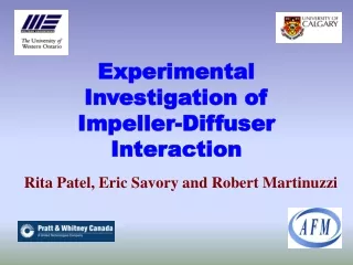
Experimental Investigation of Impeller-Diffuser Interaction Rita Patel, Eric Savory and Robert Martinuzzi
Outline • Background • Motivation • Current Work • Design of experimental rig • CFD analysis • Results and discussion • Conclusions • Future Work
Terminology Cumpsty (1978)
Impellers Radially ending Backswept Pre-swirl Above w/splitter blades Diffusers Vaneless Vaned Radial Wedge Discrete-passage Types of Impellers and Diffusers Pictures courtesy of Compressor Branch NASA Glenn Research Center
Radial Impeller Discharge • Increasing BL on shroud-suction side due to curvature • Separation • Wake on shroud-suction side • Jet displaced to hub-pressure side Jet Wake PS SS Dean and Senoo (1960), Eckardt (1976) & Krain (1981)
Diffuser Inlet • Large inlet distortions due to impeller wake • Angle and velocity fluctuations • Distortions have least effect in passage diffusers than vaned, and most in vaneless • Mixing-out of jet-wake stimulated by presence of vanes
Impeller-Diffuser Interaction • Vanes • Stationary vanes produce unsteady pressure disturbances to rotating impeller, Gallus et al. (2003) • Velocity fluctuations of 17-20% in vaneless space, Krain (1981) • Cause of backflow to impeller, Cui (2003) • Decrease traveled distance of impeller discharge distortion, Ghiglione et al. (1998)
Impeller-Diffuser Interaction (cont’d) • Radial Gap • Too small = increase backflow, Cumpsty and Inoue (1984) • Too large = less mixing-out of jet-wake Gallus et al. (2003)
Motivation • Why study impeller-diffuser interaction when numerous studies have been done? • All configurations are different • This project will lead into the study of a tandem-bladed impeller coupled with a fishtail diffuser • Study the magnitude and effect of pressure disturbances in vaneless space • Validate previously obtained CFD results Picture courtesy of Douglas Roberts (P&WC)
Current Work • Design a test facility (SCR*) that simulates a typical radial impeller exit flow field in steady state through a non-rotating cascade configuration • 5 stationary radial impeller blades • Diffuser with 5 flat plate splitters • Pipe to provide required inlet flow • Obtain LDV data of flow field *Stationary Cascade Rig
Purpose of SCR • CFD • Experimental validation of results obtained on SCR • Seeding flow distribution, flow patterns, etc… • Better understanding of how to apply LDV technique to a full-scale rig • Test use of very small optical access ports • Type of seeding for this specific flow Picture courtesy of Douglas Roberts (P&WC)
Impeller + Diffuser Close-up of impeller
Optical Access 10mm diameter 15mm diameter • Upstream Impeller Blades • Blade passages ‘hub side’
Seeding Ports Six Ports
SCR Specifications • Outlet Ma: 0.85 • Total length: 2.0 [m] • Total height:1.4 [m] • Similar physical dimensions of full-scale rig
CFD Analysis Mesh: 1.1 million tetrahedral + 0.2 million prism element mesh • ICEM CFD 10.0 with CFX 10.0 • SST k-ω model • Boundary Conditions: • Inlet: Ptotal = 172.4 [kPa] • Ttotal = 288.15 [K] • Outlet: Pstatic = 101.3 [kPa] mexpected= 0.245 kg/s mCFX= 0.242 kg/s
Mach Number Contour Plot • Impeller-diffuser only • Region of high velocity in left most passage • Obtaining close to desired Ma of 0.85 at impeller exit 50% blade height
Flow Behaviour • Shock wave at trailing edge of each blade • Passage width increasing, while height decreasing • Greater shock wave in left passage as result of diffuser sidewall
Blade Passages Migration of high velocity region to shroud suction-side and vice versa Flow behaviour similar in passages up to outlet
Pressure Contour Plot • impeller-diffuser only • Typical blade suction/pressure behaviour • Corresponding region of low pressure in left most passage Suction side Pressure side
Conclusions • From CFX results • Presence of separation in diffuser • No separation in impeller • Good flow pattern agreement between blade passages • Close agreement between theoretically calculated and CFX values at boundaries • SCR will provide a good understanding of how to apply LDV technique in a high-speed, highly-confined, compressible flow
Future Work • Experimental • Measurements in SCRF • Compare with current CFD results • Computational • Track seeding particles • Apply LDV technique and CFD model on full-scale rig at P&WC
Acknowledgements • Advanced Fluid Mechanics Research Group • http://www.eng.uwo.ca/research/afm/default.htm • Kevin Barker and Doug Phillips • University Machine Shop • Rofiqul Islam • University of Calgary • Suresh Kacker, Douglas Roberts, Feng Shi and Peter Townsend • Pratt and Whitney Canada
Thank You Questions?