Download
1 / 13
140 likes | 143 Views
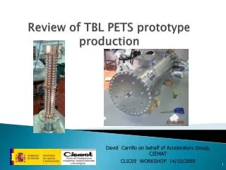
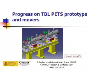
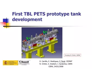
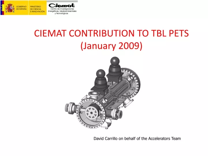
CIEMAT CONTRIBUTION TO TBL PETS (January 2009). David Carrillo on behalf of the Accelerators Team. TBL - PETS (Test Beam Line - Power Extraction & Transfer Structure). CIEMAT is responsible for TBL PETS prototype PETS should generate 12 GHz RF power in interaction with the drive beam

E N D
CIEMAT CONTRIBUTION TO TBL PETS (January 2009) David Carrillo on behalf of the Accelerators Team
TBL - PETS (Test Beam Line - Power Extraction & Transfer Structure) • CIEMAT is responsible for TBL PETS prototype • PETS should generate 12 GHz RF power in interaction with the drive beam • 16 PETS will be placed at TBL to test stability of the decelerated beam
PETS RF designs 30 GHz PETS designed by D.Carrillo (CIEMAT) & I.Syratchev (CERN) 12 GHz PETS designed by I.Syratchev (CERN) • Single choke mirror • Two waveguide extractor
PETS: General layout Fiducials Cooling pipes WR90 waveguide Copper rods Power extractor Vacuum port Supports
Copper rods • Each PETS is made of eight OFE copper rods (800 mm) • These are the most difficult parts to fabricate: overall tolerance is +/- 0.02 mm and roughness should be better than 0.4 micron • The coupling cell is smaller: two different tools are necessary • Two intermediate thermal treatments to release internal stresses Copper rod
Single rod RF test bench • A special test bench has been designed to do RF measurements on each rod • Dummy rod phase slip was 121° for 123 cells, that is, about 1° per cell • Results agree with 3-D measurements HFSS model E field and probe Mode TE10 Phase S31 vs position
RF absorbers • Several samples from different companies (SiC, AlN composite) were tested at CERN and CIEMAT • The present PETS prototype will not have absorbers. Further work is necessary for the future RF absorbers Measuring electrical properties of ceramics
Power extractor • It consists of three disks of 140 mm diameter • They will be brazed with a 1 mm wire, 78Ag22Cu alloy • The waveguides have three flanges, the two outermost of them should be vacuum tight Eight rods RF test bench • A special test bench has been designed to measure the assembly of rods • Mode launchers have been optimized to create the working mode in the PETS, using the coaxial cable coming from the network analyzer • A coaxial antenna will measure the field through the slots between the rods
Vacuum tank • 316LN CF flanges • Two pumping ports: ionic and turbo • Instrumentation ports: temperature sensors and four for assembly and free for future uses • Reference pins at the endplates Cooling • Round ¼” OFE copper pipe • 1 m/s, 0.3 bar pressure drop, four circuits, 2°C estimated temperature increase • Vacuum-tight stainless steel connectors brazed to copper pipes, using Helicoflex gaskets
CIEMAT contribution to a Race Track Microtron: LINAC David Carrillo on behalf of the Accelerators Team
RTM (Race Track Microtron) Layout • RTM IORT (Intraoperative radiation therapy ) • Electron beam up to 12 MeV • CIEMAT is responsible for LINAC (1) Electron gun (2) LINAC (3) (4)end magnets M1 & M2 (5) Quadrupole lens (6) Extraction magnets (7) Extracted beam
E field H field RTM (Race Track Microtron) LINAC design Biperiodic structure f = 5.712 GHz HFSS model Accelerating cell without nose cones for testing Cavity test RF measurements Solid works model
Conclusions • Eight 800 mm long copper rods (1 PETS) have been machined and will be assembled and measured next month • Two RF measurement benches, both for a single rod or eight ones, have been developed • No material has been identified as a good RF absorber up to now: it is necessary for CLIC PETS • CERN and CIEMAT will share the production of the next seven PETS units to be installed before the end of 2010 • CIEMAT is responsible for a small LINAC for an RTM with medical purposes