Download
1 / 62
620 likes | 757 Views
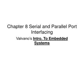
Chapter 8 Parallel Port Interfaces. 8.4 Transistors Used for Computer-Controlled Current Switches. 전류 제어 Switch(BJT). 8.4 Transistors Used for Computer-Controlled Current Switches. 8.4 Transistors Used for Computer-Controlled Current Switches.

E N D
8.4 Transistors Used for Computer-Controlled Current Switches • 전류 제어 Switch(BJT)
8.4 Transistors Used for Computer-Controlled Current Switches
8.4 Transistors Used for Computer-Controlled Current Switches
8.5 Computer-Controlled Relays, Solenoids, and DC Motors 8.5.1 Introduction to Relays
8.5.1 Introduction to Relays • 제어회로와 다른 전원으로 구동하는 Relay의 예
8.5.5 Pulse-Width Modulated DC Motors • DC 모터의속도 제어( 모터에 가해지는 실효 전력을 제어 함)를 위하여 펄스 폭 변조 기술을 사용 한다.
8.5.6 Interfacing EM Relays, Solenoids, and DC Motors Table 8.12 Maximum voltage parameter for typical snubber diodes
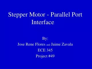
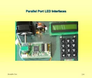
DC Motor and Stepper Controller L298N Current Motor Supply Logic Current Sensing Voltage Enable Supply Enable Sensing A Out Out Vs In A In GND Vs In B In Out Out B 1 2 1 2 3 4 1 2 3 4 5 6 7 8 9 10 11 12 13 14 15 2 7414 1 4 7414 3 470uF 35V + - +Vout 2 Motor 2 -Vout2 2 2 +Vout 1 Motor 1 -Vout1 1 + 1 + 4 4 Vs Supply Voltage GND 2W06 2W06 Vs Supply Voltage GND Vs 3 3 104 1 2 3 4 5 6 GND Dir1 En1 Dir2 En2 Vcc In Put Control Signal Connector
Dual Full-Bridge Driver L298 • High voltage : 46V • high current : 4A • Dual full-bridge driver • Accept standard TTL logic levels • Drive inductive loads such as • Relays, Solenoids, DC and, Stepping motors
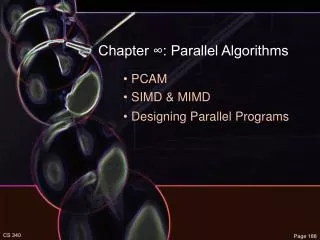
8.6.1 Stepper Motors Example Table 8.13 Stepper motor sequence
Program 8.24. A double circular linked list used to control the stepper motor. // 6811 or 6812 const struct State{ unsigned char Out; // Output const struct State *Next[2]; // CW/CCW }; typedef struct State StateType; typedef StateType *StatePtr; #define clockwise 0 // Next index #define counterclockwise 1 // Next index StateType fsm[4]={ {10,{&fsm[1],&fsm[3]}}, { 9,{&fsm[2],&fsm[0]}}, { 5,{&fsm[3],&fsm[1]}}, { 6,{&fsm[0],&fsm[2]}} }; unsigned char Pos; // between 0 and 199 StatePtr Pt; // Current State
Program 8.25. Helper functions used to control the stepper motor. // 6811 or 6812 // Move 1.8 degrees clockwise void CW(void){ Pt = Pt->Next[clockwise]; // circular PORTB = Pt->Out; // step motor if(Pos==199){ // shaft angle Pos = 0; // reset } else{ Pos++; // CW } } // Move 1.8 degrees counterclockwise void CCW(void){ Pt = Pt->Next[counterclockwise PORTB = Pt->Out; // step motor if(Pos==0){ // shaft angle Pos = 199; // reset } else{ Pos--; // CCW } } // Initialize Stepper interface void Init(void){ Pos = 0; Pt = &fsm[0]; DDRB = 0xFF; // 6812 only }
Program 8.26. High-level function to control the stepper motor. // 6811 or 6812 void Seek(unsigned char desired){ short CWsteps; if((CWsteps=desired-Pos)<0){ CWsteps+=200; } // CW steps is 0 to 199 if(CWsteps>100){ while(desired<>Pos){ CCW(); } } else{ while(desired<>Pos){ CW(); } } }