Download
1 / 7
70 likes | 201 Views
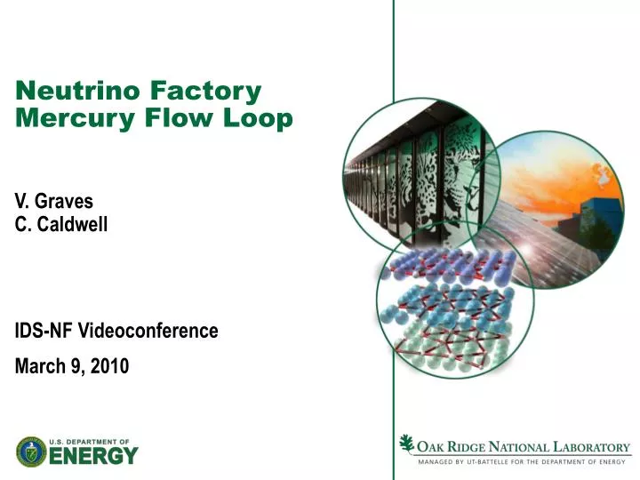
Neutrino Factory Mercury Flow Loop. V. Graves C. Caldwell IDS-NF Videoconference March 9, 2010. Flow Loop Review. 1 cm dia nozzle, 20 m/s jet requires 1.57 liter/sec mercury flow (94.2 liter/min, 24.9 gpm).

E N D
Neutrino Factory Mercury Flow Loop V. GravesC. Caldwell IDS-NF Videoconference March 9, 2010
Flow Loop Review • 1 cm dia nozzle, 20 m/s jet requires 1.57 liter/sec mercury flow (94.2 liter/min, 24.9 gpm). • MERIT experiment showed that a pump discharge pressure of ~40 bar gauge required to produce the desired jet. • Reference: SNS nominal flow 1440 liter/min (380 gpm), 7 bar gauge pump discharge pressure, ~1400 liters total Hg inventory • Basic flow scheme Pump → Nozzle → Jet/Beam Dump → Heat Exchanger → Pump
Hg Flow Overflow Mercury Drain • Minimize pressure drops through piping by increasing diameter • 2" nozzle supply piping transitioning to 1 cm nozzle • Actual NF Hg inventory may reach SNS volumes • ~500 liters in the half-length beam dump shown Mercury Pump Beam Dump Gravity Drain Flow Control Valve Heat Exchanger Storage Tank
Gravity Drain Requires Flow Control • Bulk flow exits dump via overflow drains • Gravity drain intended to remain closed until end-of run, but this liquid becomes static • Decay heating requires gravity drain to have flow control Proton Beam Mercury Jet Mercury Overflow WC Shielding Gravity Drain Flow Control Overflow drains
Target Building • Based on Study 2 concept • Mercury loop "hot cell" will probably extend into magnet chase • Could require double containment of mercury • Chase will certainly have a drain back into hot cell Decay Channel Cryostats Main Cryostat (Target Region) Core Vessel Mercury Process Hot Cell
Heat Removal • From Study 2, the mercury jet/pool receive < 10% of beam energy; bulk goes into WC shielding • Currently assumed to be WC spheres cooled by water • Much larger heat exchanger needed to cool shielding • Considering that both W and WC must be water-cooled, their effective densities will approach that of Hg. • Consequently, IF a Hg target is selected, the infrastructure will be in place to support use of Hg as a solenoid shield. • Would probably be a separate loop due to vastly different flow/pressure requirements, but could share a storage tank
Future Work • Continue development of Target Building infrastructure conceptual design • Look further into the mechanics of the region upstream of the nozzle • Remote maintenance / assembly / disassembly • Mercury flow