Download
1 / 22
220 likes | 368 Views
A Micromegas TPC for the ILC. Wenxin Wang. ILD-TPC for ILC. L: 4.7m. : 3.6m. Design for an ILD TPC in progress : Each endplate : 80 modules with 8000 pads Spatial Resolution ( in a B=3.5T magnetic field ) : δ( x ) ~ 100 μ m for the full 2.3 m drift. ILD.

E N D
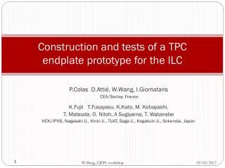
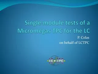
A Micromegas TPC for the ILC Wenxin Wang
ILD-TPC for ILC L: 4.7m : 3.6m Design for an ILD TPC in progress: Eachendplate: 80 modules with 8000 pads SpatialResolution (in a B=3.5T magneticfield): δ(x) ~ 100 μm for the full 2.3 m drift ILD
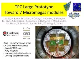
Large Prototype-TPC (LP-TPC) Magnet up to 1.2T Field cage: 61 cm length and 72 cm diameter 7 interchangeable modules with keystone shape
MPGD: Micromegas & GEM Several types of readout modules are studied GEM (test with 3 modules) Micromegas (test with 7 modules)
Micromegas with Resistive Anode Pad width limits MPGD TPC resolution Charge dispersion technique with a resistive anode so that wide pads can be used for centroid determination : pad width 0 : resolution at Z=0 without diffusion resistive foil glue pads mesh mesh B E B E pads Direct signal readout technique
Micromegasmodule • Module size: 23 cm × 17 cm • 24 rows × 72 columns • Readout: 1726 Pads • Pad size: ~3 mm × 7 mm
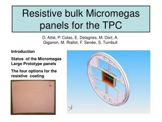
Micromegasmodules Resistive Kapton ~3 MΩ/□ Resistive Kapton ~5 MΩ/□ Standard Resistive ink ~3 MΩ/□
Uniformity MeanResidualvs RowNumber Z-independentdistortions Distortions up to 50 microns for resistiveink (blue points) Rms 7 microns for CLK film (red points) Z=5cm Z=35cm Z=50cm Row Number
Beam test 2012~2013: Test with multi-modules Integrated electronics (23cm× 17cm × 5cm ) 2008~2011: Test with one module T2K electronics (32cm× 25cm × 14cm ) ResistiveMicromegas Detector FEM Fullyintegrated Module FEC
Event display Online monitor 2D or 3D display software available Offline monitor
Drift Velocity • Test in 2009 (B=0T): • T2K gas: Ar:CF4:iso=95:3:2 • T=19oC - P = 1035hPa • H2O:35ppm AtE=230 V/cm : Vdrift= 7.698 +- 0.040 cm/µs (Magboltz : 7.583+-0.025(gascomp.)) The differenceis 1.5+-0.6 %
Gain Study Gain ADC For 6.84 mm pitch and 5 GeVe- Expectations for Ntot: 61.9 (from HEED simulation)
Test bench EnergyResolution:~13% rms Gain ~2600 (usingcollimatedsource, Vmesh=380V) The 55Fe source is put in an aluminum collimation tube and fixed on a set of two mechanical arms (X-Y).
Spatial resolution Event selection
Spatial resolution Hits selection (c) Fit track after selection hits (row 35) Row number (b) Fit track without using hit in row 35 Row number (a) Fit track with all rows X (mm) X (mm) : supposed residual of the detector : the fitted hit position in test row : the position of track crossing the test row
Spatial resolution B=1 T Cd = 94.2µm/√cm (Magboltz)
Compare with GEM ( Spatial resolution )
Field distortions B=1T After alignment B=0T B=0T
Field distortions B=1T Distortions at different drift distances in B=0T or B=1T B=0T
Conclusion • A lot of experience has been gained in building and operating Micromegas TPC panels. • The characteristics of the Micromegasmodules, such as the uniformity, energy resolution, stability have been studied in detail. • 7 modules have been successfully tested with full integration of the electronics at the same time. • Thanks to the resistive technology, the measured resolution is about 60 microns at zero drift distance with 3 mm wide pads. This meets ILC needs. • Distortions are observed. Their detailed study will allow to correct them and improve the design to minimize them.