Download
1 / 33
330 likes | 492 Views
Implanting a Computer Control System in Accelerators. May 30, 2006 Bucharest , ROMANIA. Oded Heber Department of Particle Physics Weizmann Institute of Science 76100, Rehovot ISRAEL. OUTLINE. General Introduction to Weizmann Institute Introduction to Accelerators Computer Control Systems

E N D
Implanting a Computer Control System in Accelerators May 30, 2006 Bucharest , ROMANIA Oded Heber Department of Particle Physics Weizmann Institute of Science 76100, Rehovot ISRAEL
OUTLINE • General Introduction to Weizmann Institute • Introduction to Accelerators Computer Control Systems • Upgrading and new system concepts • New System (in new accelerator) • Upgrading an existing system • Installing new system in an old accelerator • The WI Pelletron system and other labs. • Summary
Weizmann – Facts and Figures • Established on 1934 • 2500 people • 250 research groups • 1000 MSc, PhD students and postdocs • 850 scientific support staff • 80 buildings on 1.2 sq. km. • Budget (2005): about $185 Million/year (32% by the government).
Nature 430, 311-316 (15 July 2004) 25% of the country Science is done at WI
Yeda – WI technology transfer company Yeda became a world leader in Technology Transfer • Tens of products from Weizmann on the market. • Total annual royalty-generating sales in 2004: $6,000,000,000. • Over 40 new companies where established around Yeda’s technologies (some already public), 18 in the last 5 years.
What is a computer control system for accelerator ? The ability to control and maintain a full process using computers: • Industrial - manufacture floor, fab • Civil, Public – traffic control, electricity • Scientific oriented facility – accelerators, nuclear reactor
Communication bus Control bus Field bus PLC and I/O cards Sensors – I/O points server clients Definition: SCADA Acronym for supervisory control and data acquisition, a computer system for gathering and analyzing real time data hardware
SCADA Software • Control of many (103-105) I/O points • Continues communication with many busses (RS485, GPIB, Ethernet, modbus…) and PLCs (usually OPC server). • Data logging – data bases • Security • Process control (PID) • Alarms • Graphical interface • Flexibility • Connectivity to nonstandard and scientific instruments
What is special in SCADA for accelerators (for basic science) ? • Research facility – flexible • Many nonstandard and prototype equipments • Timing - synchronization (bunching, coincidence) • Physicist proof system
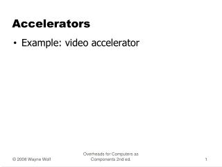
Computer Control Accelerator Hardware (Software) Trends Off the shelf instruments Home made instruments Home made controller Industrial PLC CAMAC - VME “large” computers PDP , IBM Mini computers VAX Personal computers Industrial scada Fortran, Assembler EPICS
Example Case 1: a system for new accelerator SARAF 40 MeV super conductor LINAC at Soreq NRC ISRAEL Accelerator purchased from Accel GmbH, Bergisch-Gladbach, Germany
SARAF Main Control System (MCS) – General Architecture Accelerator Beam Lines Radiation Safety System (RSS) Cryogenics Building and General Safety Applications S7, FP, PXI S7, FP S7-F S7 S7 FP, VME I/O Network Ethernet Servers for: Accelerator, Beam Lines, RSS, Cryogenics, Building, Applications Server for: Backup, Data Logging Client Network Ethernet Servers located in Server Room Clients located in MCR and throughout facility and Soreq Servers and Client computers running LabVIEW + DSC + OPC Operator Clients User Clients Soreq Clients Development Clients
Main Control System (MCS) Realization Guidelines (1) • Choose Commercial Software • Established companies • Widely used software in control applications • No need to write custom drivers • Choose Commercial Hardware • Hardware incorporating OPC standard • Companies that produce both hardware and software • Minimize types of Hardware and Software • Optimize with sub-contractor constrains • Settle for several types if inter-communication possible
Main Control System (MCS) Realization Guidelines (2) • Choose Server-Client architecture • Improves reliability • May provide redundancy • Consider backup server with a smooth automatic transition in case of main server crash • Client crash should not affect server or other clients • Computers and Hardware on one network • Use Fiber Optics in EM-noisy environments
Main Control System (MCS) Realization Decisions • Software- LabVIEW with DSC module and OPC server • LabVIEW is flexible and scientific oriented • Client licenses are not so expensive and do not depend on number of I/O channels • Hardware – FieldPoint, PXI from NI and S7, S7-F from Siemens • All types are chosen due to sub-contractor constraints • All types are OPC compatible • S7-F compatible with international safety standards • Network and Buses – Ethernet
A Possible LabVIEW DSC Main Screen Main panel Main selection Sub selection Functional panel Alarm panel
Case 2: Upgrading existing CC system • Change I/O points ? • Change PLCs ? (CAMAC to Industrial) • Change software or upgrading (experience) • Change computers ?(VAX to PC) • Change OS ? (VMS, Unix to Linux, Windows) • Money? • Shutdown time?
Case 3 : Installing a system for the first time Example: 14UD Pelletron ( and VDG) Goal: All the controls and indicators should be integrated in the CC system. Changing accelerator parameters (different masses different energies) in a minute time scale with high stability (AMS requirements).
constrains • Money • Manpower • Continue normal operation + maintenance • Controls in high voltages high pressure environment (14 MV terminal, 120kV source, SF6 gas).
solution • Bottom up philosophy - first select the I/O point R/W solution. • Connect first the points that are already at the old control room, afterwards the “easy points” and the most important ones. • Select Hardware that are most common used in electrostatic accelerators and easy to expand.
Group3 Control Features • Fiber Optics - high voltage isolation – noise immunity. • Small Size - easy mounting - keep wiring short to minimize noise pickup. • High Resolution - 16 bit analogs • High Update Rate - scan rates of up to 32,000 channels per second • High channel Density - several thousand channels per computer slot • Diagnostic Port - on device interfaces for system development and debugging.
5 loops 1000 I/O GPIB, RS232 DAQ 1 loop 100 I/O 1 loop 200 I/O RS232 DAQ 19 PLC’s RS485
Software and OS • LabVIEW by NI (start at version 3.1) • Computer PC + windows (start with WIN 3.11 on one 486 machine) • Few Upgrades to LabVIEW DSC (7.0 and 8.0 – full SCADA) • 15 P-IV computers in server client architecture.
control room Laser room Linear trap Bent trap Ion sources Source control
SUMMARY • Computer control system is a crucial part for any accelerator. • SCADA selection depends on many constraints such as money, manpower, laboratory expertise and third party constructors. • The trend is to use industrial hardware, PC computers and commercial SCADA software.