Download
1 / 21
210 likes | 369 Views
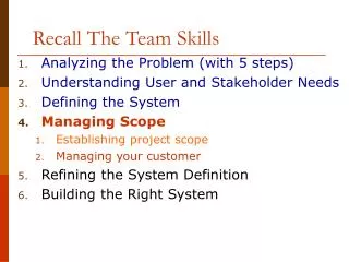
Recall The Team Skills. Analyzing the Problem (with 5 steps) Understanding User and Stakeholder Needs Defining the System Managing Scope Refining the System Definition Building the Right System. Building the Right System. Ch 25. From Use Cases to Implementation

E N D
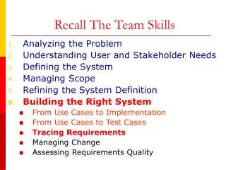
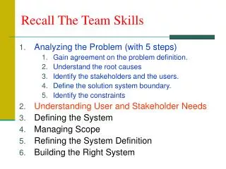
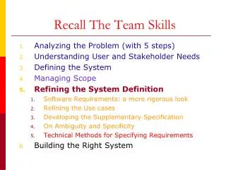
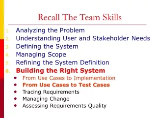
Recall The Team Skills • Analyzing the Problem (with 5 steps) • Understanding User and Stakeholder Needs • Defining the System • Managing Scope • Refining the System Definition • Building the Right System
Building the Right System • Ch 25. From Use Cases to Implementation • Ch 26. From Use Cases to Test Cases • Ch 27. Tracing Requirements • Ch 28. Managing Change • Ch 29. Assessing Requirements Quality in Iterative Development
Chapter 25From Use Cases to Implementation The Orthogonality Problem Use Cases realization in the Design Model Collaboration From Design to Implementation
The Orthogonality Problem • It's probably fairly straightforward to find, inspect, and validate the code that fulfills requirements such as • "Support up to an eight-digit floating-point input parameter" • However, things get a little trickier for requirements such as • "The system shall handle up to 100,000 trades an hour"
The Orthogonality Problem • There is little correlation between the requirement and the design and implementation; they are orthogonal, or nearly so. • In other words, the form of our requirements and the form of our design and implementation are different. • There is no one-to-one mapping to make implementation and validation easier.
Reasons of orthogonality problem • Requirements speak of real-world item, while code speaks about stacks, queues, and algorithms. • Some requirements (like non-functional req.s) have little to do with logical structure of code. • Some functional req.s require other parts of the system to interact with. • Good system design is more related to resources management, reusing code, and applying purchased components.
Avoiding Orthogonality problem • By using object-orientation ..why? • Reuse • No changes in real world items implies no changes in code • Abstraction and moving from classes to objects • Classes collaboration
Architecture of Software Systems • Software Architecture involves • Description of elements from which the systems are built, interactions amongst those elements, patterns that guide their composition, and constraints on those patterns. (Shaw and Garlan, 1996) • Why architecture? • understand what the system does • Understand how it works • Think and work on pieces of the system • Extend the system • Reuse parts of the system to build another one
The “4+1” views of Architecture • Different groups of stakeholders need to see the architecture from different views • Kruchten (1995) “4+1” views: • Logical view: the functionality of the system • Implementation view: source codes, libraries, object classes, .. etc • Process view: operations of the system and interfaces with others • Deployment view: operating systems and platforms • Use case view: ties all views together
The “4+1” views of Archtiecture End User Functionality Logical view Implementation view Programmer Software Management Use case view Designer/Tester Behavior Process view Deployment view System Engineering System topology Delivery, installation communication System Integrators Performance Scalability Throughput
HOLIS Case Study • Logical view: describes the various classes and subsystems that implemented behavior • Implementation view: describes the various code artifacts for HOLIS • Process view: demonstrate how multitasking is done • Deployment view: how HOLIS is distributed across CCU, Control switch, homeowner’s PCs.
Realizing Use Cases in the Design Model • Use cases are realized via collaborations, which are societies of classes, interfaces, subsystems, or other elements that cooperate to achieve some behavior. • A common UML stereotype, the use-case realization, is used for this purpose: A special form of collaboration, one that shows how the functionality of a specific use case is achieved in the design model. • Symbolic representation of a collaboration • Example
Structural and Behavioural Aspects of Collaborations • Collaborations have two aspects: • A structural part that specifies the static structure of the system (the classes, elements, interfaces, and subsystems on which the implementation is structured). • A behavioral part that specifies the dynamics of how the elements interact to accomplish the result.
Structural and Behavioural Aspects of Collaborations • A class diagram represents the structural aspects, whereas an interaction diagram (sequence or collaboration) represents the behavioural aspects.
Class Diagram for the HOLIS Emergency Message Sequence Collaboration
Behavioral Aspects of the HOLIS Emergency Message Sequence Collaboration
Using Collaborations to Realize Sets of Individual Requirements
From Design to Implementation • By modeling the system this way, we can ensure that the significant use cases and requirements of the system are properly realized in the design model. • In turn, this helps ensure that the software design conforms to the requirements. • The next step follows quite logically, although admittedly not easily. • The classes and the objects defined in the design model are further refined in the iterative design process and eventually implemented in terms of the physical software components—source files, binaries, executables, and others—that will be used to create the executable software.
Key Points • Some requirements map well from design to implementation in code. • Other requirements have little correlation to design and implementation; the form of the requirement differs from the form of the design and implementation (the problem of orthogonality). • Object orientation and use cases can help alleviate the problem of orthogonality. • Use cases drive design by allowing all stakeholders to examine the proposed system implementation against a backdrop of system uses and requirements. • Good system design is not necessarily optimized to make it easy to see how and where the requirementsare implemented.