Download
1 / 27
410 likes | 762 Views
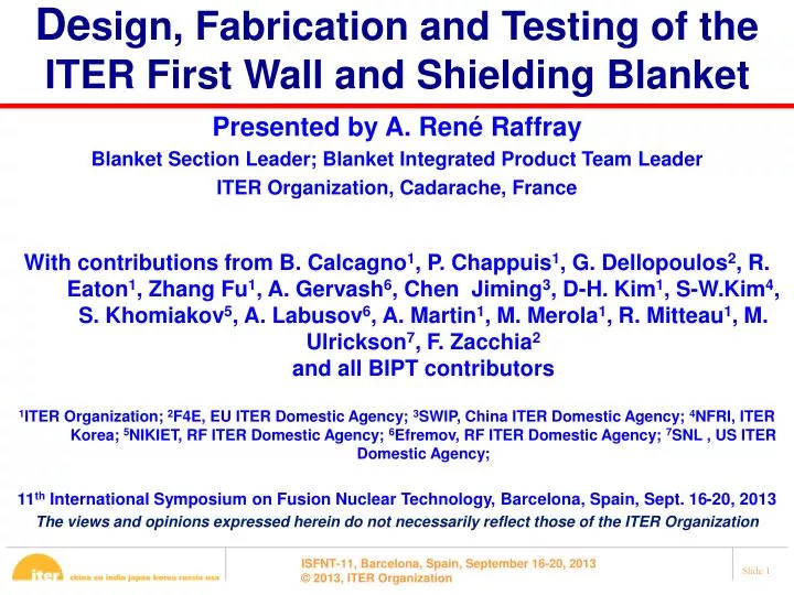
De sign, Fabrication and Testing of the ITER First Wall and Shielding Blanket. Presented by A. René Raffray Blanket Section Leader; Blanket Integrated Product Team L eader ITER Organization, Cadarache , France

E N D
Design, Fabrication and Testing of the ITER First Wall and Shielding Blanket • Presented by A. René Raffray • Blanket Section Leader; Blanket Integrated Product Team Leader • ITER Organization, Cadarache, France • With contributions from B. Calcagno1, P. Chappuis1, G. Dellopoulos2, R. Eaton1, Zhang Fu1, A. Gervash6, Chen Jiming3, D-H. Kim1, S-W.Kim4, S. Khomiakov5, A. Labusov6, A. Martin1, M. Merola1, R. Mitteau1, M. Ulrickson7, F. Zacchia2and all BIPT contributors • 1ITER Organization; 2F4E, EU ITER Domestic Agency; 3SWIP, China ITER Domestic Agency;4NFRI, ITER Korea;5NIKIET, RF ITER Domestic Agency; 6Efremov, RF ITER Domestic Agency; 7SNL , US ITER Domestic Agency; • 11th International Symposium on Fusion Nuclear Technology, Barcelona, Spain, Sept. 16-20, 2013 • The views and opinions expressed herein do not necessarily reflect those of the ITER Organization
Blanket Effort Conducted within BIPT Blanket Integrated Product Team DA’s - CN - EU - KO - RF - US ITER Organization • Include resources from Domestic Agencies to help in major design and analysis effort. • Direct involvement of procuring DA’s in design - Sense of design ownership - Would facilitate procurement
Blanket System Functions Main functions of ITER Blanket System: • Contribute in absorbing radiation and particle heat fluxes from the plasma • Contribute in providing shielding to reduce heat and neutron loads in the vacuum vessel and ex-vessel components • Provide a plasma-facing surface which is designed for a low influx of impurities to the plasma • Provide limiting surfaces that define the plasma boundary during startup and shutdown • Provide passage for the plasma diagnostics
Blanket System Modules 7-10 • The Blanket System consists of Blanket Modules (BM) comprising two major components: a plasma facing First Wall (FW) panel and a Shield Block (SB). Modules 11-18 Modules 1-6 50% 50% 50% 40% 10% Blanket Module 100% SB Attachment to VV ~850 – 1240 mm SB (semi-permanent) FW Panel (separable)
Blanket System in Numbers Number of Blanket Modules: 440 Max allowable mass per module: 4.5 tons Total Mass: 1530 tons First Wall Coverage: ~600 m2 Materials: - Armor: Beryllium - Heat Sink: CuCrZr - Steel Structure: 316L(N)-IG - Axial attachment (bolt/cartridge) Alloy 718 - Pad Al Bronze - Insulating layer Alumina Max total thermal load: 736 MW Cooling water conditions: 4 MPa and 70°C
Impact of Interface Requirements on Blanket Design • Interface requirements impose challenging demands on the blanket in particular since the blanket is in its pre-PA phase whereas several major interfacing components are already in procurement. • Such demands include: - Accommodating plasma heat loads on FW - Maintaining acceptable load transfer to the vacuum vessel - Providing sufficient shielding to the vacuum vessel and TF coils - Accommodating the space allocations for in-vessel coils, manifolds and plasma heating systems. • These are highlighted in subsequent slides as part of the blanket design description.
Inboard Module Shape and Size Optimized for Neutron Shielding of VV and TF Coil • • The blanket is a major contributor to neutron shielding of the coils and vacuum vessel. • • e.g. to enhance shielding, blanket-related modifications were introduced following PDR: • a flat inboard profile • an addition of 4 cm to mid-plane radial thickness • a reduction of the vertical gaps between inboard SB’s from 14 to 10 mm. • • This has resulted in lowering the integrated heating in the coil to from 17 to 15.7 kW (as compared to a target of 14 kW) • An assessment indicates that this could still allow fusion power close to the design value of 500MW for a 1800s rep period without any adjustment of the cryo-plant operating conditions.
Design of First Wall Panel Impacted by Accommodation of Plasma Interface Requirements I-shaped beam to accommodate poloidal torque
Shaping of First Wall Panel • Heat load associated with charged particles is a major component of heat flux to first wall. • The heat flux is oriented along the field lines. • Thus, the incident heat flux is strongly design-dependent (incidence angle of the field line on the component surface). • Shaping of FW to shadow leading edges and penetrations. Plasma - Allow good access for RH - Shadow leading edges Exaggerated shaping RH access
Plasma Loads to the First wall • Combination of steady-state and off-normal loads • Design based on steady-state loads and maximum armor thickness • Beryllium surface damage accepted during off-normal events • Learn from early operation before moving to higher power scenarios to minimize off-normal events with major impact on FW armor lifetime
First Wall Panels: Design Heat Flux • 218 Normal heat flux panels EU • 222 Enhanced heat flux panels RF, CN
Normal Heat Flux (NHF) First Wall Normal Heat Flux Finger: • q’’ = 2 MW/m2 • Steel Cooling Pipes • HIP’ing Normal Heat Flux Semi-Prototype SS Back Plate SS Pipes CuCrZr Alloy Be tiles
Enhanced Heat Flux (EHF) First Wall Enhanced Heat Flux Finger: • q’’ = 4.7 MW/m2 • Hypervapotron • Explosion bonding (SS/CuCrZr) + brazing (Be/CuCrZr) EHF FW Semi-Prototype Be tiles Hypervapotron (HVT) Laser welding Brazing Bimetallic structure CuCrZr/SS 316L(N)-IG Central welding Coolant channel lid (Steel 316L(N)-IG) External welding Finger body (Steel 316L(N)-IG) Laser welding
Shield Block Design • Slits to reduce EM loads and minimize thermal expansion and bowing • Cooling holes are optimized for Water/SS ratio (Improving nuclear shielding performance). • Cut-outs at the back to accommodate many interfaces (Manifold, Attachment, In-Vessel Coils).
Shield Block Full-Scale Prototypes KODA: SB08 CNDA: SB14 (example of some processes) • Basic fabrication method from a single high-quality forged steel block and includes drilling of holes, welding of cover plates for water headers, and final machining of the interfaces.
Shield Block Attachment • 4 flexible axial supports • Keys to take moments and forces • Electrical straps to conduct current to vacuum vessel e.g. BM 4 Interfaces FIRST WALL SHIELD BLOCK INTERMODULAR PADS ELECTRICAL STRAPS (SB & FW) FLEXIBLE CARTRIDGE MANIFOLD CENTERING PADS
Flexible Axial Support FSP for testing (NIKIET, RF) • 4 flexible axial supports located at the rear of SB, where nuclear irradiation is lower. • Compensate radial positioning of SB on VV wall by means of custom machining. •Cartridge and bolt made of high strength Alloy-718 • Designed for 800 kN preload to take up to 600 kN Category III load.
Keys in Inboard and Outboard Modules to Accommodate Moments and Forces from EM Loads • Each inboard SB has two inter-modular keys and a centering key to react the toroidal forces. • Each outboard SB has 4 stub keys concentric with the flexible supports. • Bronze pads are attached to the SB and allow sliding of the module interfaces during relative thermal expansion. • Key pads are custom-machined to recover manufacturing tolerances of the VV and SB.
Pads and Insulating Layer Scheme of Testing Inter-Modular Key pads on Inboard Test Samples: Al-bronze, plasma sprayed Al2O3 • Pads moved to Shield Block to minimize impact on VV interfaces • Electrical insulation of the pads through ceramic coating on their internal surfaces. • Cylindrical pads for IMK; rectangular pads for stub keys • Insulating layer performance determined by R&D (8000 cycles at 1.5 MN and 1 run at 2 MN))
Shield Block and Attachment Designed to Respect Pre-Defined Load from Vacuum Vessel Load Specifications • •Optimizing blanket design (radial thickness and slitting) to reduce EM loads based on the following analysis: • - DINA analysis of disruptions and VDEs • - Eddy and halo analysis to obtain superposition of wave forms • Dynamic analysis of BM structural response using ANSYS (NIKIET) • • For example, results for BM 1 (one of the most loaded modules) show that the loads on the keys are within the VV LS for Cat. II and Cat. III cases
Interface with Blanket Manifold and In-Vessel Coils • • A multi-pipe manifold configuration has been chosen, with each pipe feeding one or two BM’s • - Higher reliability due to minimization of welds and utilization of seamless pipes. • - Superior leak localization capability due to larger segregation of cooling circuits. • - Elimination of drain lines. • • In-Vessel coils: three sets of ELM control coils per outboard sector to control ELMs by applying an asymmetric resonant magnetic perturbation to the plasma surfaceand 2 sets of vertical stability (VS) coils for plasma stabilization. • • BMs to be designed with cut-outs to accommodate these space reservations. Multi-pipe Manifold Configuration VS coils ELM coils Example outboard SB 12 with manifold and ELM coil cut-outs
Interface with Neutral Beam System • The NB region with the neutron bean injection ports create a particular geometry challenge for the blanket design •Special modules have been developed to accommodate this as well as the other design constraints • The NB shine-through also needs to be accommodated by the impacted Blanket Modules
FW 16 to Accommodate Neutral Beam Shine-Through • Detailed Model done following EHF FW guidelines (central-slot insert not shown here for simplicity). • Special shaping to accommodate shine-though beam and protect slot. • Analysis assessment performed to verify stress compliance with SDC-IC (ITER structural design criteria) for both M-type (monotonic) and C-type (cyclic) damage.
Supporting R&D • A detailed R&D program has been planned in support of the design, covering a range of key topics, including: - Critical heat flux (CHF) tests on FW mock-ups. - Experimental determination of the behavior of the attachment and insulating layer under prototypical conditions. - Material testing under irradiation. - Demonstration of the different remote handling procedures. • A major part of the R&D effort is the qualification program for the SB and FW panels. - Full-scale SB prototypes (KODA and CNDA). - FW semi-prototypes (EUDA for the NHF FW Panels, and RFDA and CNDA for the EHF First Wall Panels). - Qualification tests include: He leak test, pressure test, FW heat flux test
Procurement Schedule • FDR: April 2013 (successfully held) • FDR Approval: July 2013 (ahead of schedule) • *End date = delivery of last component to ITER site
Summary • The Blanket design is extremely challenging, having to accommodate high heat fluxes from the plasma, large EM loads during off-normal events and demanding interfaces with many key components (in particular the VV and IVC) and the plasma. • Substantial re-design following the ITER Design Review of 2007. The Blanket CDR, PDR and FDR have confirmed the correctness of this re-design. • Effort now focused on finalizing the design work based on input received at the FDR and to prepare for procurement starting at the end of 2013. • Parallel R&D program and DA pre-qualification process by the manufacturing and testing of full-scale or semi-prototypes.
Latest Blanket Major Milestone • Blanket FDR successfully held in April 2013