Download
1 / 14
140 likes | 287 Views
TIDS 15, Sant Feliu de Guixols , 1-5 September 2013. Electron tunneling between surface states and implanted Ge atoms in Si-MOS structures with Ge nanocrystals. Issai Shlimak. Jack and Pearl Resnick Institute of Advanced Technology,

E N D
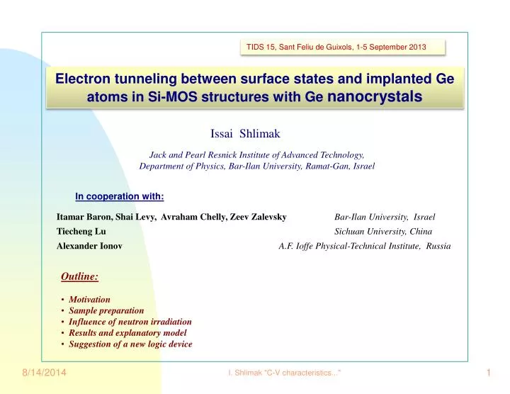
TIDS 15, SantFeliu de Guixols, 1-5 September 2013 Electron tunneling between surface states and implanted Ge atoms in Si-MOS structures with Genanocrystals Issai Shlimak Jack and Pearl Resnick Institute of Advanced Technology, Department of Physics, Bar-Ilan University, Ramat-Gan, Israel In cooperation with: Itamar Baron, Shai Levy, Avraham Chelly, Zeev ZalevskyBar-Ilan University, Israel Tiecheng Lu Sichuan University, China Alexander Ionov A.F. Ioffe Physical-Technical Institute, Russia • Outline: • Motivation • Sample preparation • Influence of neutron irradiation • Results and explanatory model • Suggestion of a new logic device I. Shlimak "C-V characteristics..."
Motivation MOS structures with NC-Ge embedded into an insulating SiO2 layer on a Si substrate are considered a perspective material for nano-size novel electronic devices, such as nonvolatile memory units. This is due to hysteresis of C-V characteristics caused by charge trapping in nanocrystals. In most of the reviewed works, the thickness of SiO2 layer was relatively small (30-50nm) and NC-Ge were distributed throughout the SiO2 layer, (sometimes even penetrating into the Si substrate). This leads to conclusion that the main mechanism of NC-Ge charging is electron transfer from the Si substrate. Vice versa, properties of Si substrate could be influenced by implanted Ge atoms. Typical high frequency C-V of p-Si MOS without and with NC-Ge, (adopted from Appl. Phys. Lett. 82,1212 (2003). The main goal of this work was to eliminate the mutual influence NC-Ge and Si substrate, for which a special series of samples have been fabricated with NC-Ge layer spatially separated from Si/SiO2 interface. I. Shlimak "C-V characteristics..."
Motivation MOS structures with NC-Ge embedded into an insulating SiO2 layer on a Si substrate are considered a perspective material for nano-size novel electronic devices, such as nonvolatile memory units. This is due to hysteresis of C-V characteristics caused by charge trapping in nanocrystals. In most of the reviewed works, the thickness of SiO2 layer was relatively small (30-50nm) and NC-Ge were distributed throughout the SiO2 layer, (sometimes even penetrating into the Si substrate). This leads to conclusion that the main mechanism of NC-Ge charging is electron transfer from the Si substrate. Vice versa, properties of Si substrate could be influenced by implanted Ge atoms. Typical high frequency C-V of p-Si MOS without and with NC-Ge, (adopted from Appl. Phys. Lett. 82,1212 (2003). The main goal of this work was to eliminate the mutual influence NC-Ge and Si substrate, for which a special series of samples have been fabricated with NC-Ge layer spatially separated from Si/SiO2 interface. Sample preparation 1)Thick ( 640 nm) amorphous SiO2 films were initially grown on the <100> oriented p-Si substrates. 2) Ge+ ions with high dose 1017 cm-2 were implanted into SiO2 layer. The ion energy was 150 keV which corresponds to the projection range 100 nm and the half-width of spatial distribution 30 nm. As a result, implanted Ge layer in the form of single atoms and amorphous clusters was located under the SiO2 surface and far from Si/SiO2 interface. 3) Gold spots with diameter 0.3 mm were deposited on top of the SiO2 layer to form the MOS structures. 4) Ge nanocrystals (NC-Ge) with average diameter of 4-10 nm appear only after sample annealing at 8000C HR-TEM image of NC-Ge layer. inset shows the image of a single Ge NC I. Shlimak "C-V characteristics..."
MOS structures under study Four types of MOS structures were studied 1) “Initial” samples (a p-Si MOS structure with thick SiO2 layer, before ion implantation) 2) “Implanted” samples, (afterGe+ ion implantation, before annealing), without NC-Ge 3) “NC-Ge” samples, with NC-Ge (afterannealing at 800oC) 4) “Irradiated” samples, NC-Ge samples that were irradiated with neutrons dose1020 cm-2 followed by annealing of radiation damage at 8000C. I. Shlimak "C-V characteristics..."
MOS structures under study Four types of MOS structures were studied 1) “Initial” samples (a p-Si MOS structure with thick SiO2 layer, before ion implantation) 2) “Implanted” samples, (afterGe+ ion implantation, before annealing), without NC-Ge 3) “NC-Ge” samples, with NC-Ge (afterannealing at 800oC) 4) “Irradiated” samples, NC-Ge samples that were irradiated with neutrons dose1020 cm-2 followed by annealing of radiation damage at 8000C. C-V characteristics were measured at high frequencies (100kHz and 1MHz) S-shape U-shape U-Hysteresis return of S-shape I. Shlimak "C-V characteristics..."
Explanatory model S-shape U-shape accumulation V < 0 C = C0 To the best of our knowledge, U-shape of C-V has never been observed in MOS structures at high frequencies. depletion V 0 CCmin (1/C)=(1/ C0)+(1/Cdep) inversion V > 0 C C0 at low f (<104Hz) C = Cmin at high f (>105Hz) minority carriers I. Shlimak "C-V characteristics..."
Explanatory model S-shape U-shape accumulation V < 0 C = C0 To the best of our knowledge, U-shape of C-V has never been observed in MOS structures at high frequencies. This effect can be understood taking into account : location of Ge atoms close to the surface and far from the Si/SiO2 interface. We believe that the U-shape of C-V is due to electron tunneling between surface states and Ge atoms. depletion V 0 CCmin (1/C)=(1/ C0)+(1/Cdep) The applied voltage Vtilts the top of potential barrier between surface and the nearest Ge atoms which leads to enhancement of the electron tunneling from the surface states to Ge atoms. This increases the positive surface charge Qand therefore also the measured capacitance C = ∂Q/∂V. Only Ge atoms nearest to the surface can participate in the charging because the probability of tunneling exponentially drops with distance. This limits the increase of Q and leads to the capacitance saturation. As a result, the layer of Ge atoms becomes negatively charged and partially screens the electric field at the Si/SiO2 interface. inversion V > 0 C C0 at low f (<104Hz) C = Cmin at high f (>105Hz) minority carriers I. Shlimak "C-V characteristics..."
NC-Ge samples Formation of NC-Ge makes tunneling easier and leads to C-V hysteresis due to charge trapping in NC-Ge. The fact that hysteresis is not observed in “implanted” samples shows that single Ge atoms and amorphous clusters cannot hold the charge I-V characteristics Electron tunneling between surface and NC-Ge leads to appearance of an additional transport channel along the surface “initial” sample, R0 = 2 GΩ “NC-Ge” sample, R0 = 400 MΩ and falls down to 80 MΩ at |V| > 5V I. Shlimak "C-V characteristics..."
Neutron irradiation and second annealing Ge space distribution in “NC-Ge”” samples Return of S-shape After neutron irradiation and annealing at 8000C Before neutron irradiation Restoring the S-shape indicates that tunneling between surface states and nearest NC-Ge is suppressed. This means that Ge atoms and nanocrystals are removed from the vicinity of the surface!. Removal of NC-Ge from the surface was directly observed in HR-TEM images and using EDS (energy dispersive elemental spectroscopy). What happened to the Ge atoms? HR-TEM of “irradiated” sample EDS of “irradiated” sample I. Shlimak "C-V characteristics..."
Neutron irradiation and second annealing Ge space distribution in “NC-Ge”” samples Return of S-shape After neutron irradiation and annealing at 8000C Before neutron irradiation Restoring the S-shape indicates that tunneling between surface states and nearest NC-Ge is suppressed. This means that Ge atoms and nanocrystals are removed from the vicinity of the surface!. Removal of NC-Ge from the surface was directly observed in HR-TEM images and using EDS (energy dispersive elemental spectroscopy). What happened to the Ge atoms? Ge atoms were detected on the SiO2 surface of “irradiated” samples in the form of Ge oxide and elemental Ge by XPS . This means that redistribution of NC is caused by an enhanced diffusion of Ge atoms toward SiO2 surface during annealing of radiation damage after fast neutron irradiation. XPS (X-ray photoelectron spectroscopy) of SiO2 surface. (a) – “NC-Ge” sample, (b) – “irradiated” sample HR-TEM of “irradiated” sample EDS of “irradiated” sample I. Shlimak "C-V characteristics..."
Possible application Light illumination White light generates the electron-hole pairs across NC-Ge and Si forbidden bands which significantly decreases variation of the surface charge due to the applied voltage. Combination of U-shape and Hysteresis suggests a possibility of a novel 2-bit (4-digit) logic memory cell controlled by either electrical switching or light illumination τ ~ t 0.76 Current time of relaxation τas a function of time of observation t. Voltage and light-induced switching of “NC-Ge” MOS structure Kinetics of the capacitance decay after the gate voltage is switched off I. Shlimak "C-V characteristics..."
Summary • A series of p-Si based MOS structures were fabricated with NC-Ge embedded into a thick SiO2 layer. • Three distinctive features of the samples should be noted: • thick SiO2 (640 nm) layer; • high density of implanted Ge ions (1017 cm-2); • location of implanted Ge atoms near the surface and far from Si/SiO2 interface • C-V measurements of the obtained MOS structures showed the following effects: • S-shape of C-V characteristics in “initial” samples was replaced by U-shape after Ge ion implantation; • Formation of NC-Ge in “implanted” samples led to C-V hysteresis due to charge trapping in NC-Ge; • An explanatory model of U-shape based on assumption of electron tunneling between SiO2 surface states and nearest Ge atoms is discussed. • S-shape of C-V was recovered after neutron irradiation and annealing of radiation damage which was explained by suppression of electron tunneling caused by removal of Ge atoms away from the surface. • Combination of U-shape and hysteresis opens the possibility for a new optoelectronic device based on optically controlled 2-bit (4-digit) • memory retention unit I. Shlimak "C-V characteristics..."
THANK YOU! THANK YOU! C-V characteristics of Si-MOS structures with Ge nanocrystals Electron tunneling between surface states and implanted Ge atoms in Si-MOS structures with Ge nanocrystals Issai Shlimak Jack and Pearl Resnick Institute of Advanced Technology, Department of Physics, Bar-Ilan University, Ramat-Gan, Israel Issai Shlimak Jack and Pearl Resnick Institute of Advanced Technology, Department of Physics, Bar-Ilan University, Ramat-Gan, Israel I. Shlimak "C-V characteristics..."
Temperature dependence of I-V and C-V in “NC-Ge” samples I-V characteristics, Temperature increases (from bottom to top) from 300C to 1200C C-V characteristics, Temperature increases (from bottom to top) from 300C to 2500C I. Shlimak "C-V characteristics..."


![INTOSAI Financial Audit Guidelines (ISSAI 1000-2999) Presentation by [name and title]](https://cdn3.slideserve.com/5884213/slide1-dt.jpg)