Download
1 / 233
2.34k likes | 2.77k Views
Digital Logic Design and Application ( 数字逻辑设计及应用 ). Chapter 7 Sequential Logic Design Principles ( 时序逻辑设计原理 ). Latches and Flip-Flops ( 锁存器和触发器 ) Clocked Synchronous State-Machine Analysis ( 同步时序分析 ) Clocked Synchronous State-Machine Design ( 同步时序设计 ). Introduction.

E N D
Digital Logic Design and Application (数字逻辑设计及应用) Chapter 7 Sequential Logic Design Principles( 时序逻辑设计原理 ) Latches and Flip-Flops (锁存器和触发器 ) Clocked Synchronous State-Machine Analysis (同步时序分析) Clocked Synchronous State-Machine Design (同步时序设计)
Introduction Combinational circuit Outputs depend solely on the present combination of the circuit inputs’ values b=0 F=0 b=0 F=0 b=1 F=1 Digital Digital Digital System System System if b=0, then F=0 if b=1, then F=1 b=1 F=1 Digital System (a) b=0 F=1 Digital System Cannot determine value of F solely from present input value (b) • Vs. sequential circuit: Has “memory” that impacts outputs too
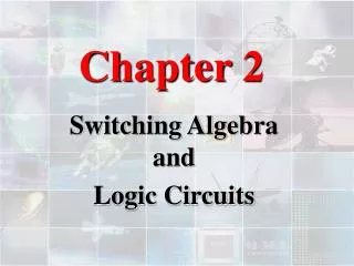
Digital Logic Design and Application (数字逻辑设计及应用) Basic Concepts (基本概念) Logic Circuits are Classified into Two Types (逻辑电路分为两大类): • Combinational Logic Circuit (组合逻辑电路) • Sequential Logic Circuit (时序逻辑电路)
Digital Logic Design and Application (数字逻辑设计及应用) Basic Concepts (基本概念) • Combinational Logic Circuit (组合逻辑电路) Outputs Depend Only on its Current Inputs. (任何时刻的输出仅取决与当时的输入) Character of Circuit: No Feedback Circuit, No Memory Device (电路特点:无反馈回路、无记忆元件)
Digital Logic Design and Application (数字逻辑设计及应用) Basic Concepts (基本概念) • Sequential Logic Circuit (时序逻辑电路) Outputs Depend Not Only on its Current Inputs, But also on the Past Sequence of Inputs. (任一时刻的输出不仅取决与当时的输入, 还取决于过去的输入序列) Character of Circuit: Have Feedback Circuit, Have Memory Device (电路特点:有反馈回路、有记忆元件)
Digital Logic Design and Application (数字逻辑设计及应用) Basic Concepts (基本概念) • Sequential Logic Circuit (时序逻辑电路) Finite-State Machine: Have Finite States. (有限状态机:有有限个状态。) A Clock Signal is Active High if state changes occur at the clock’ Rising Edge or when the clock is High, and Active Low in the complementary case. (时钟信号高电平有效是指在时钟信号的上升沿或时钟的高电平期间发生变化。)
Digital Logic Design and Application (数字逻辑设计及应用) Basic Concepts (基本概念) • Sequential Logic Circuit (时序逻辑电路) Clock Period: The Time between Successive transitions in the same direction. (时钟周期:两次连续同向转换之间的时间。) Clock Frequency: The Reciprocal of theClock Period (时钟频率:时钟周期的倒数。) Figure 7-1
Digital Logic Design and Application (数字逻辑设计及应用) Basic Concepts (基本概念) • Sequential Logic Circuit (时序逻辑电路) Clock Tick: The First Edge of Pulse in a clock period or sometimes the period itself. (时钟触发沿:时钟周期内的第一个脉冲边沿,或时钟本身。) Duty Cycle: The Percentage of time that the clock signal is at its asserted level. (占空比:时钟信号有效时间与时钟周期的百分比。) Figure 7-1
X0 Y0 X2 Y2 X1 Y1 X0 Y0 X1 Y1 Xn Yn 串 行 加 法 器 X Y CI CO S 反馈 X Y CI CO S X Y CI CO S X Y CI CO S C1 C2 0 C C2 C1 C3 C2 C0 C1 S0 S1 Sn S0 S1 S2 Digital Logic Design and Application (数字逻辑设计及应用) 思考:能否只用一片1位 全加器进行串行加法?? 利用反馈和时钟控制
X0 Y0 Xi Yi X1 Y1 Xn Yn 串 行 加 法 器 暂存 时钟控制 X Y CI CO S X Y CI CO S X Y CI CO S X Y CI CO S C1 C1 0 C Ci Ci+1 S0 S1 Sn Si Digital Logic Design and Application (数字逻辑设计及应用) 利用反馈和时钟控制 需要具有记忆功能的逻辑单元,能够暂存运算结果。
Q Q Q_L Q_L Digital Logic Design and Application (数字逻辑设计及应用) 7.1 Bistable Elements (双稳态元件) 1 0 0 1 1 0 0 1 It has Two Stable State: Q = 1 ( HIGH) and Q = 0 ( LOW) (电路有两种稳定状态:Q = 1 ( 1态) 和 Q = 0 ( 0态)) —— Bistable Circuit(双稳电路)
Q Q Q_L Q_L Digital Logic Design and Application (数字逻辑设计及应用) 7.1 Bistable Elements (双稳态元件) 1 0 0 1 1 0 0 1 When Power is first Applied to the circuit, it Randomly Comes up in One State or the Other and Stays there Forever. ( 只要一接电源,电路就随机出现两种状态中的一种, 并永久地保持这一状态。)
Vout1 Vout2 Vin2 Vin1 Vout1 亚稳态 metastable 稳态 stable Q = Vin2 Q_L Vin2 Vout2 Vout2 Vin1 Vin2 = Vout2 Digital Logic Design and Application (数字逻辑设计及应用)
Q Q_L Digital Logic Design and Application (数字逻辑设计及应用) Metastable Behavior(亚稳态特性) Random Noise will tend to Drive a circuit that is Operating at the Metastable Point toward one of the Stable operating point. ( 随机噪声会驱动工作于亚稳态点的电路转移到一个稳态的工作点上去 )
稳态 稳态 Digital Logic Design and Application (数字逻辑设计及应用) Metastable Behavior(亚稳态特性) Apply a definite Pulse Width from a Stable state to the Other. (从一个“稳态”转换到另一个“稳态” 需加一定宽度的脉冲(足够的驱动)) 亚稳态 所有的时序电路对亚稳态都是敏感的
Digital Logic Design and Application (数字逻辑设计及应用) 7.2 Latches and Flip-Flops(锁存器与触发器) ——The Basic Building Blocks of most Sequential Circuits. (大多数时序电路的基本构件) • Latches(锁存器) • 根据输入,直接改变其输出(无使能端) • 有使能端时,在使能信号的有效电平之内都可根据输入直接改变其输出状态
Digital Logic Design and Application (数字逻辑设计及应用) 7.2 Latches and Flip-Flops(锁存器与触发器) ——The Basic Building Blocks of most Sequential Circuits. (大多数时序电路的基本构件) • Flip-Flops( F/F,触发器) • 只在时钟信号的有效边沿改变其输出状态
Digital Logic Design and Application (数字逻辑设计及应用) 7.2 Latches and Flip-Flops(锁存器与触发器) • S-R Latch (S-R锁存器) • S-R Latch with Enable (具有使能端的S-R锁存器) • D Latch (D锁存器) • Edge-Triggered D Flip-Flops (边沿触发式D触发器) • Edge-Triggered D Flip-Flops with Enable (具有使能端的边沿触发式D触发器)
Digital Logic Design and Application (数字逻辑设计及应用) 7.2 Latches and Flip-Flops(锁存器与触发器) • Scan Flip-Flops (扫描触发器) • Master/Slave Flip-Flops (S-R、J-K) (主从式触发器) • Edge-Triggered J-K Flip-Flops (边沿触发式J-K触发器) • T Flip-Flop (T触发器)
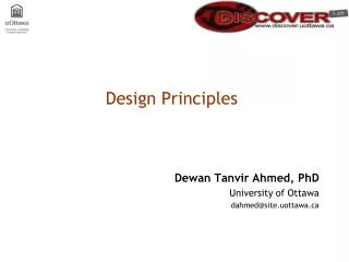
0 R Q 或非门 非门 Q QL QL S 0 Digital Logic Design and Application (数字逻辑设计及应用) S-R Latches (S-R锁存器) 工作原理: (1)S = R = 0 电路维持原态 Qn+1 = Qn QLn+1 = QLn 新 态 原 态
1 1 R 0 0 1 1 Q R Q 0 1 0 (a) (b) QL S QL 0 S 0 0 Digital Logic Design and Application (数字逻辑设计及应用) S-R Latches (S-R锁存器) Reset 工作原理: 0 (2)S = 0, R = 1 锁存器清0:Qn+1=0 QLn+1=1 即使S,R无效(=0) 锁存器仍能锁定0态 1 a. 原态:Qn=0,QLn=1 新态:Qn+1=0,QLn+1=1 b. 原态:Qn=1,QLn=0 新态:Qn+1=0,QLn+1=1 1
0 0 R 0 1 0 0 Q R Q 1 0 1 (a) (b) QL S QL 0 S 1 1 Digital Logic Design and Application (数字逻辑设计及应用) S-R Latches (S-R锁存器) Set 工作原理: 1 (3)S = 1, R = 0 锁存器置1:Qn+1=1 QLn+1=0 即使S,R无效(=0) 锁存器仍能锁定1态 0 a. 原态:Qn=1,QLn=0 1 新态:Qn+1=1,QLn+1=0 b. 原态:Qn=0,QLn=1 新态:Qn+1=1,QLn+1=0
R 0 1 “禁止” Q 0 Q QL S 0 QN 1 0 Digital Logic Design and Application (数字逻辑设计及应用) S-R Latches (S-R锁存器) 工作原理: (3)S = R = 1 Qn+1 = QLn+1 = 0 当S,R无效(=0)时, 亚稳态,对噪声敏感 状态不确定
R Reset (清0) 状态转移真值表 (逻辑符号) (逻辑符号) S Q R QL (功 能 表) Q S R Q QL S Q R Q S R Qn Qn+1 (置1) 0 0 0 1 1 0 1 1 维持原态 0 1 1 0 0* 0* 0 0 0 0 0 1 0 1 0 0 1 1 1 0 0 1 0 1 1 1 0 1 1 1 0 1 0 0 1 1 0* 0* QL S Set Digital Logic Design and Application (数字逻辑设计及应用) S-R Latches (S-R锁存器) Logic Symbol Function Table
Qn+1 0 S=0 R=X 0 状态转移真值表 S=1,R=0 0 S=X R=0 1 1 特征 方程 SR S=0,R=1 00 01 11 10 1 Qn 0 1 S R Qn Qn+1 0 1 0 0 0 0 0 1 0 1 0 0 1 1 1 0 0 1 0 1 1 1 0 1 1 1 0 1 0 0 1 1 0* 0* Digital Logic Design and Application (数字逻辑设计及应用) Qn+1 = S + R’·Qn S·R = 0 约束条件 状态图
S R Q QL S R Q S R Q QL 0 0 0 1 1 0 1 1 维持原态 0 1 1 0 0* 0* tpHL(RQ) tpw(min) tpLH(SQ) Digital Logic Design and Application (数字逻辑设计及应用) 最小脉冲宽度 传播延迟 Figure 7-8
锁存器进入亚稳态 Digital Logic Design and Application (数字逻辑设计及应用) S-R锁存器的动作特点 • 输入信号在全部有效电平内,都能直接改变锁存器的状态(直接置位-复位触发器) • 输入端需遵守约束条件 • 抗干扰能力最低 • 当S=R=1,然后同时取消时 • S和R端输入信号脉冲宽度过小 • S和R端输入信号同时取反
7.4(7.2) 7.5(7.3) 7.7(7.5) 7.12(7.9) 7.13(7.10) 7.16(7.13) 7.17(7.14) 7.18(7.15) 7.19(7.16) 7.20(7.19) 7.21(7.20)(c) 7.41(7.27) 7.43(7.28) 7.46(7.34) 7.51(7.47) 7.52(7.49) 7.77(7.68) 第7章作业
S R Digital Logic Design and Application (数字逻辑设计及应用) Draw the Output Waveform of the S-R Latch A Class Problem ( 每课一题 ) Q
Digital Logic Design and Application (数字逻辑设计及应用) Chapter 7 Sequential Logic Design Principles( 时序逻辑设计原理 ) Latches and Flip-Flops (锁存器和触发器 ) Clocked Synchronous State-Machine Analysis (同步时序分析) Clocked Synchronous State-Machine Design (同步时序设计)
稳态 Q 亚稳态 稳态 Q_L Digital Logic Design and Application (数字逻辑设计及应用) Review of Last Class (内容回顾) • 时序逻辑电路 • 输出取决于输入和过去状态 • 电路特点:有反馈回路、有记忆元件 • 双稳态元件 注意:亚稳态特性 0态 和 1态
R Q Q Q_L QL S Digital Logic Design and Application (数字逻辑设计及应用) Review of Last Class (内容回顾) • 时序逻辑电路 • 输出取决于输入和过去状态 • 电路特点:有反馈回路、有记忆元件 • 双稳态元件 如何加入控制信号?? 0态 和 1态
S S_L S-R锁存器功能表 逻辑符号 Q S Q R Q S_L R_L Q QL 1 1 1 0 0 1 0 0 维持原态 0 1 1 0 1* 1* QL R_L R Digital Logic Design and Application (数字逻辑设计及应用) S-R latch(锁存器) 清0 置1 不定 电路维持原态 S_L = R_L = 1 S_L = 1, R_L = 0 Q = 0, QL = 1 S_L = 0, R_L = 1 Q = 1, QL = 0 S_L = R_L = 0 Q=QL=1,不定状态
S_L 逻 辑 符 号 S S C R 功能表 Q Q C S R Q QL Q C 维持原态 维持原态 0 1 1 0 1* 1* 0 X X 1 0 0 1 0 1 1 1 0 1 1 1 QL R R_L Digital Logic Design and Application (数字逻辑设计及应用) S-R Latch with Enable(具有使能端的S-R锁存器) —— 又称“时钟S-R锁存器” (1). C = 0时: 维持原态 (2). C = 1时: 与S-R锁存器相似 注意:当S=R=1时,若C由10, 则下一状态不可预测。
Q C C S R Q QL 0 X X 1 0 0 1 0 1 1 1 0 1 1 1 维持原态 维持原态 0 1 1 0 1* 1* S R Digital Logic Design and Application (数字逻辑设计及应用) 时钟S-R锁存器时序图 动作特点:输入信号在时钟(使能端)有效期间,都能直接改变触发器的状态。
D锁存器功能表 D S 逻辑符号 Q = D Q C D Q QL D Q C Q C 1 0 0 1 1 1 1 0 0 X 保持 QL R Digital Logic Design and Application (数字逻辑设计及应用) D Latch (D锁存器) 数据 输入端 控制端 ENABLE CLK 输出状态保持不变 C = 0, 输出随输入状态而改变 C = 1, When D = 1,Q = 1 When D = 0,Q = 0 Transparent Latch (透明锁存器)
Level-Sensitive D Latch SR latch requires careful design to ensure SR=11 never occurs D latch relieves designer of that burden Inserted inverter ensures R always opposite of S D latch D Q D S S1 C Q D latch symbol C Q R1 R
Level-Sensitive D Latch 1 D latch D D S 0 S1 1 C 0 C 1 S1 0 Q 1 R1 0 R1 R 1 Q 0
0 D=0 状态转移真值表 D=1 D=1 1 D=0 D Qn+1 0 1 0 1 Digital Logic Design and Application (数字逻辑设计及应用) Function Description of a D Latch(D锁存器的功能描述) 特征方程:Qn+1 = D(C=1) 状态图
S R Q QL S R Q S R Q QL 0 0 0 1 1 0 1 1 维持原态 0 1 1 0 0* 0* tpHL(RQ) tpw(min) tpLH(SQ) Digital Logic Design and Application (数字逻辑设计及应用) 最小脉冲宽度 传播延迟 Figure 7-8
Q C D tpLH(DQ) tsetup thold tpHL(DQ) tpLH(CQ) tpHL(CQ) Setup Time (建立时间) Hold Time (保持时间) Digital Logic Design and Application (数字逻辑设计及应用) Timing Parameters for a D Latch (D锁存器的时序图) 在C的下降沿附近有一个时间窗 这段时间内D输入一定不能变化
EN_L C TG TG QL D A B CMOS传输门 EN TG Q Digital Logic Design and Application (数字逻辑设计及应用) D Latch with CMOS Transmission Gate(利用CMOS传输门的D锁存器)
C Q_L TG1 QL D Q TG2 Q Digital Logic Design and Application (数字逻辑设计及应用) D Latch with CMOS Transmission Gate(利用CMOS传输门的D锁存器) C = 0 TG1 断开 TG2 连通 保持原态
C 功能表 C D Q QL TG1 QL D 1 0 0 1 1 1 1 0 0 X 保持 TG2 Q Digital Logic Design and Application (数字逻辑设计及应用) D Latch with CMOS Transmission Gate(利用CMOS传输门的D锁存器) C = 1 TG1 连通 TG2 断开 QL = D’ Q = D
D Q C Q D Q C Q D Q C Q D Q C Q WR DIN[3:0] RD DOUT[3:0] Digital Logic Design and Application (数字逻辑设计及应用) Applicationsof Latches(锁存器的应用)
Xi Yi Ci Xi Yi X Y CI S CO Si Ci+1 暂存 时钟控制 X Y CI CO S Q D Q C Ci Ci+1 Si Digital Logic Design and Application (数字逻辑设计及应用) Applicationsof Latches(锁存器的应用) 串行输入、串行输出 注意:时钟同步 CLK 再谈串行输入 加法器的实现
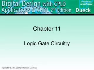
Storing One Bit Example Requiring Bit Storage Flight attendant call button Press call: light turns on Stays on after button released Blue light Call button Call button Blue light 1 Bit Storage Bit Storage Cancel button Cancel button 2. Call button released – light stays on 1. Call button pressed – light turns on 1 3.2 a
Storing One Bit – Flip-FlopsExample Requiring Bit Storage Press cancel: light turns off Stays off after button released Logic gate circuit to implement this? Call button Blue light Bit Storage Cancel button 3. Cancel button pressed – light turns off 3.2 0 Q Call Cancel Doesn’t work. Q=1 when Call=1, but doesn’t stay 1 when Call returns to 0 Need some form of “feedback” in the circuit 48
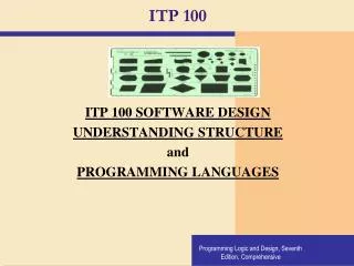
First attempt at Bit Storage Need some sort of feedback Does circuit below do what we want? Q S t 49
First attempt at Bit Storage No: Once Q becomes 1 (when S=1), Q stays 1 forever – no value of S can bring Q back to 0 S 0 S 1 S 1 S 0 1 S Q Q Q Q Q 1 0 1 0 0 0 1 1 1 0 t t t t t 1 S 0 1 t 0 1 Q 0