Download
1 / 11
110 likes | 309 Views
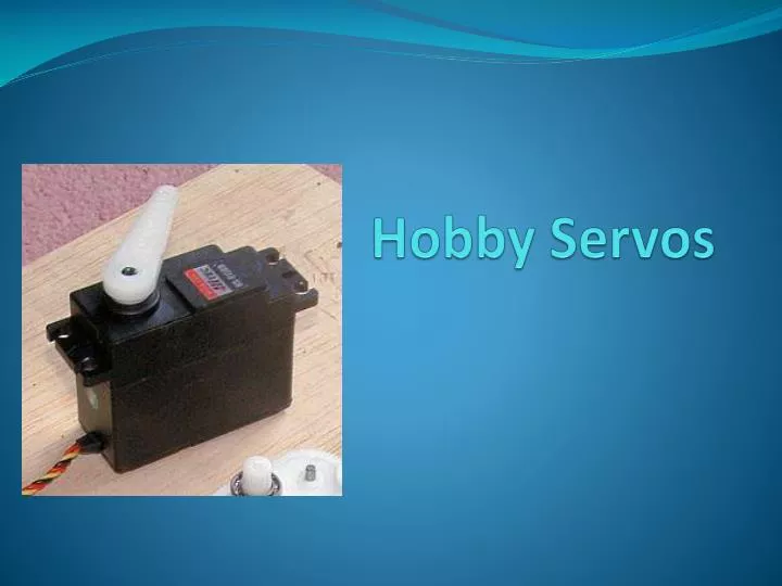
Hobby Servos. Servo Background. Servos provide control of rotary position Servos are used extensively in the remote control hobby world for: Aircraft (flaps, ailerons, throttle, landing gear…) Cars and trucks (steering) Boats (rudder, sail sheets)

E N D
Servo Background • Servos provide control of rotary position • Servos are used extensively in the remote control hobby world for: • Aircraft (flaps, ailerons, throttle, landing gear…) • Cars and trucks (steering) • Boats (rudder, sail sheets) • Servos are used with varying degrees of success on ROVs because they are not usually waterproof enough to withstand long periods at depth • Nonetheless, they present some possibilities for ROV enthusiasts. Consider for example, camera tilt control in a sealed tube
How Servos Work • Inside a servo case, the key components are: • Control circuitry • A motor driving reduction gears • A potentiometer driven by the reduction gears that extends through the housing and drives the actuator • An external control signal indicates the angle that the servo should move to and the motor responds by running until the potentiometer reaches the desired position • A servo requires three wires, GND, power, and the control line
How Servos Work Actuator Reduction gears Potentiometer Motor Control circuit
Considerations in Selecting a Servo • Hundreds of models of servo are available • Selection parameters include • Operating voltage (4.8-6V is typical but some run at 7.2V) • Digital or analog (digital have better/faster positioning) • Maximum torque • Rotation speed • Number of rotations (180° is typical but other ranges including multi-turn and continuous turn are available) • Physical size • Material gears are made of • Material bearings are made of • Waterproof???? • Price
The R/C Servo Control Signal • Communication of desired position is encoded as the width of a 0-5V digital pulse • The pulse is repeated about 50 times each second • The pulse varies between 1ms and 2ms • 1ms is interpreted as fully one way and 2ms as fully in the other direction • 1.5ms means position in the middle (or stop for continuous rotation)
The R/C Servo Control Signal Pulse anywhere from 1-2ms Repeat about every 20ms 5V VOLTAGE (V) 0V 1ms 2ms 20ms TIME (ms)
Controlling a Servo with an Arduino • Arduino has functions available for controlling servos • Servo functions are drawn from a Servo library • Servos are positioned by setting a pin as a servo output and then sending a value from 0-180 specifying the rotation required • View Jeremy Blum’s Tutorial 5 for an example of how to program a servo using the Arduino
Motor Control Using Servo Signals • Many R/C hobby manufacturers have Electronic Speed Controllers (ESCs)that can control motor speed using servo signals • Not all ESCs can drive a motor in reverse as is required for ROVs • Ensure that the ESC is able to handle the voltage and current you require (note that references to cells should be interpreted as 1.2V/cell, i.e. NiCd battery cell voltages thus a 4 cell ESC is 4.8V) • If you have an appropriate ESC, motor speed control is identical to servo control except that 1ms (value of 0 on Arduino) might be full reverse, 2ms (180 on Arduino) may be full forward while 1.5ms (90 on Arduino) is stopped. • Of course there many other speeds are possible between these values
Test Your Knowledge • Write an Arduino sketch to: • Read an analog value from pin A0 • Attach a potentiometer between 0 and 5V with the wiper connected to pin A0 (this could be another resistive sensor/resistor combination) • Scale the analog value appropriately to control the brightness of an LED attached to pin 3 • Scale the analog value appropriately to control the position of a servo attached to pin 9 (or equivalently the speed of a motor attached to an ESC controlled by the signal at this pin) • Your sketch should be similar to the that on the following slide
//* AnalogReadSerialAnalogWriteServoOut Reads an analog input on pin 0, prints the result to the serial monitor. Analog input also sets servo position (orESC motor speed) and LED brightness Attach the center pin of a potentiometer (or other sensor/resistor combination) to pin A0, and the outside pins to +5V and ground. This example code is in the public domain. */ #include <Servo.h> //tell C where to get the servo routines Servo demoServo; // define a variable of type Servo and call it demoServo intservoPin = 9; // we will use pin 9 for servo output (could also ESC) int led=3; //we will use pin 3 for analog write to change LED brightness // the setup routine runs once when you press reset: void setup() { Serial.begin(9600);// initialize serial communication at 9600 bits per second: demoServo.attach(servoPin); //initialize servo functions on pin named servoPin } // the loop routine runs over and over again forever: void loop() { intsensorValue = analogRead(A0);// read the input on analog pin 0: analogWrite(led,sensorValue/4); // scale 0-1023 to 0-255 for analog write demoServo.write(sensorValue*180.0/1023.0); //scale 0-1023 to 0-180 for servo Serial.println(sensorValue); // print out the value you read: delay(1); // delay in between reads for stability }